Protocol based vlan configuration example – Allied Telesis AlliedWare Plus Operating System Version 5.4.4C (x310-26FT,x310-26FP,x310-50FT,x310-50FP) User Manual
Page 427
VLAN Introduction
Software Reference for x310 Series Switches
C613-50046-01 REV A
AlliedWare Plus
TM
Operating System - Version 5.4.4C
16.15
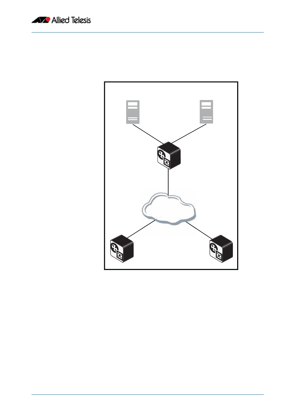
Protocol based VLAN configuration example
A protocol based VLAN topology is shown below in
See the configuration procedure to configure Switch A in
on the next page.
Figure 16-3: Protocol based VLAN configuration
Switch A has the following configuration to enable protocol based VLAN classification:
■
VLAN 100 and VLAN 101 created and applied to port1.0.2 and port1.0.3 respectively
■
IPv4 and IPv6 VLAN classifier rules created and mapped to VLAN 100 and VLAN 101
■
VLAN classifier group created and mapped to port1.0.1
■
VLAN 100 and VLAN 101 are trunked over port1.0.2 and port1.0.3 respectively
■
IPv4 packets received on port1.0.1 go to port1.0.2 VLAN 100
■
IPv6 packets received on port1.0.1 go to port1.0.3 VLAN 101
The configuration procedure in
show the steps to configure Switch A.
protocol_VLAN_1
IPv6 packets
IPv4 packets
VOIP Server
VLAN 100
VLAN101
Switch A
port1.0.1
Internet Server
port1.0.2
port1.0.3
Customer Network
IPv4 packets go to
port1.0.2 VLAN100
IPv6 packets go to
port1.0.3 VLAN101
IPv6 packets
IPv4 packets