Introduction, Ring components and operation, Introduction ring components and operation – Allied Telesis AlliedWare Plus Operating System Version 5.4.4C (x310-26FT,x310-26FP,x310-50FT,x310-50FP) User Manual
Page 1484
EPSR Introduction and Configuration
Software Reference for x310 Series Switches
57.2
AlliedWare Plus
TM
Operating System - Version 5.4.4C
C613-50046-01 REV A
Introduction
Ethernet Protection Switching Ring (EPSR) is a protection system that prevents loops
within Ethernet ring based topologies. EPSR offers a rapid detection and recovery time (in
the order of 50 ms, depending on configuration) if a link or node fails. This rapid recovery
time makes EPSR a more effective alternative to spanning tree options when using ring-
based topologies to create high speed resilient Layer 2 networks.
Ring Components and Operation
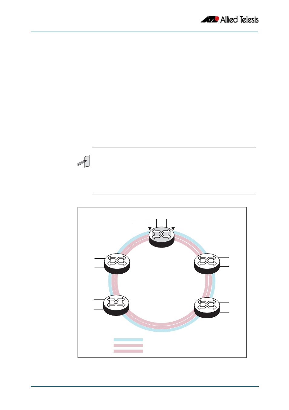
EPSR operates only on ring-based topologies. An EPSR ring comprises a series of nodes
(Ethernet bridges) connected end to end. The figure below shows a basic ring
configuration. A ring comprises one master node and a number of transit nodes. Each
node connects to the ring via two ports. On the master node one port is configured to be
the primary port and the other, the secondary port.
Figure 57-1: Simple EPSR ring configuration
Note
x310 Series switches within an EPSRing can only operate as Transit Nodes. To
form an EPSR ring using x310 Series switches, you will need to use an
alternative Allied Telesis switch, such as an x610 Series switch or an x510 Series
switch with a Premium License, as the master node.
In the configuration examples shown later in this chapter, master node
configuration is included for completeness; however, the commands shown
will need to be applied to the switch selected to be the master node.
Da
ta V
LA
N
_2
Dat
a V
LA
N_
1
Con
tro
l VL
AN
Master
Node
Transit
Node
4
Data VLAN_1
Control VLAN
Primary Port
Transit
Node
3
EPSR 1.eps
Control VLAN
Data VLAN_2
P
S
Secondary Port
Control VLAN “forwarding”
Data VLAN “forwarding”
End User Ports
Transit
Node
2
End User Ports
End User Ports
End User Ports
Data VLAN_2
Transit
Node
1
End User Ports
Control VLAN “forwarding”
Data VLAN“blocked”
P
S
Data VLAN_1