Renesas SH7781 User Manual
Page 941
19. Display Unit (DU)
Rev.1.00 Jan. 10, 2008 Page 911 of 1658
REJ09B0261-0100
19.3.44
Plane n Blinking Time Register (PnBTR) (n
= 1 to 6)
The plane n blinking time registers (PnBTR, n = 1 to 6) set the display interval length for plane n.
When the PnBM bit in PnMR is set to the auto display change mode (blinking mode), by setting,
in this register, the length of the interval of display of PnDSA0R and PnDSA1R, blinking
operation is performed using PnDSA0R and PnDSA1R.
When 1 is set, PnDSA0R and PnDSA1R are switched for each field.
When 0 is set, operation is the same as when set to 1.
R/W:
Internal update:
R/W:
Internal update:
16
17
18
19
20
21
22
23
24
25
26
27
28
29
31
30
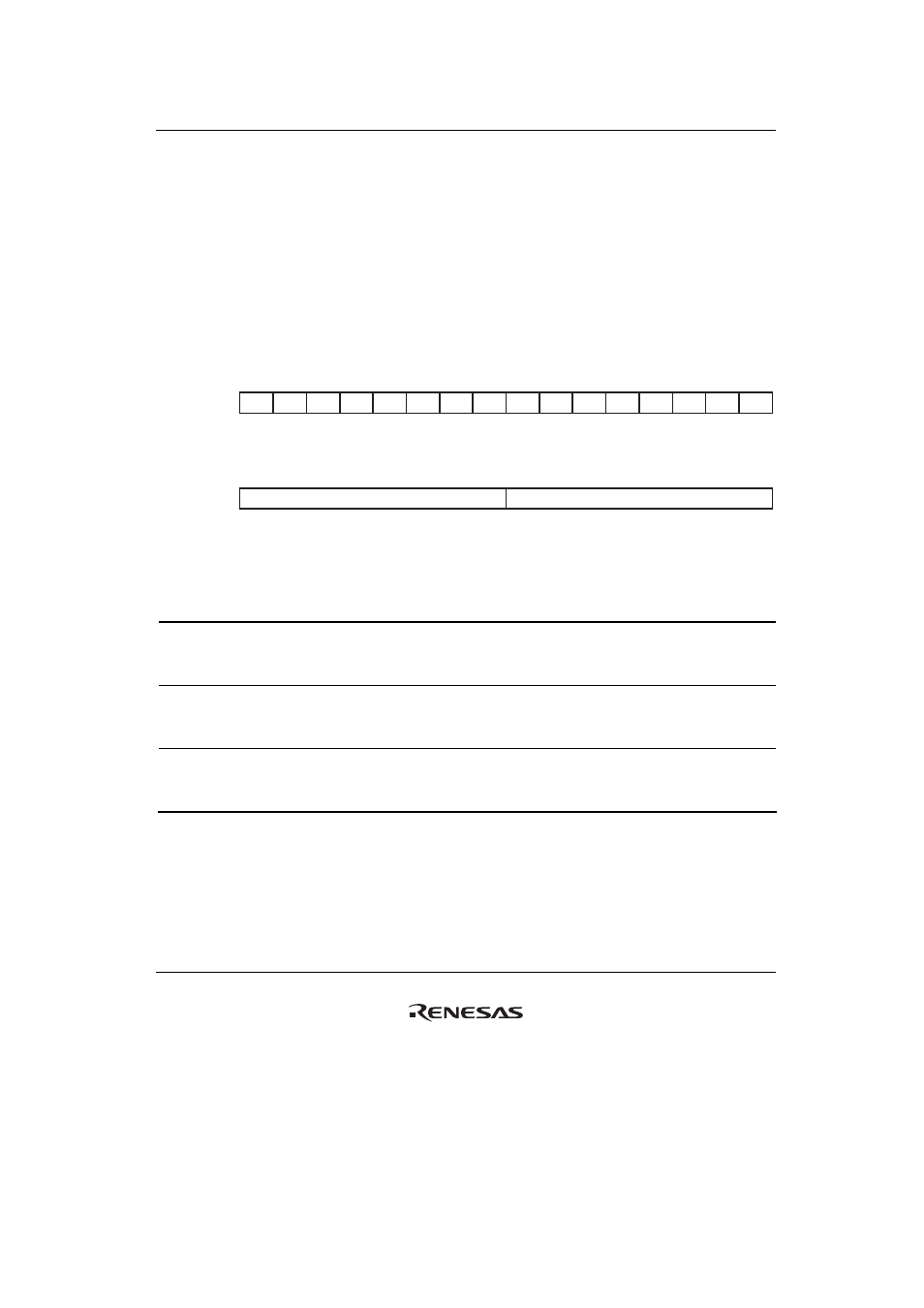
Bit:
Initial value:
R
R
R
R
R
R
R
R
R
R
R
R
R
R
R
R
0
0
0
0
0
0
0
0
0
0
0
0
0
0
0
0
—
—
—
—
—
—
—
—
—
—
—
—
—
—
—
—
R/W
R/W
R/W
R/W
R/W
R/W
R/W
R/W
R/W
R/W
R/W
R/W
R/W
R/W
R/W
R/W
O
O
O
O
O
O
O
O
O
O
O
O
O
O
O
O
1
0
0
0
0
0
0
0
1
0
0
0
0
0
0
0
PnBTB
PnBTA
0
1
2
3
4
5
6
7
8
9
10
11
12
13
15
14
Bit:
Initial value:
Bit Bit
Name
Initial
Value R/W
Internal
Update Description
31 to 16
⎯ All
0
R
⎯ Reserved
These bits are always read as 0. The write value
should always be 0.
15 to 8
PnBTA
H'01
R/W
Yes
Plane n Blinking Time A
The length of the interval of display of PnDSA0R
should be set in field units.
7 to 0
PnBTB
H'01
R/W
Yes
Plane n Blinking Time B
The length of the interval of display of PnDSA1R
should be set in field units.