2 bus control register (bcr) – Renesas SH7781 User Manual
Page 397
11. Local Bus State Controller (LBSC)
Rev.1.00 Jan. 10, 2008 Page 367 of 1658
REJ09B0261-0100
11.4.2
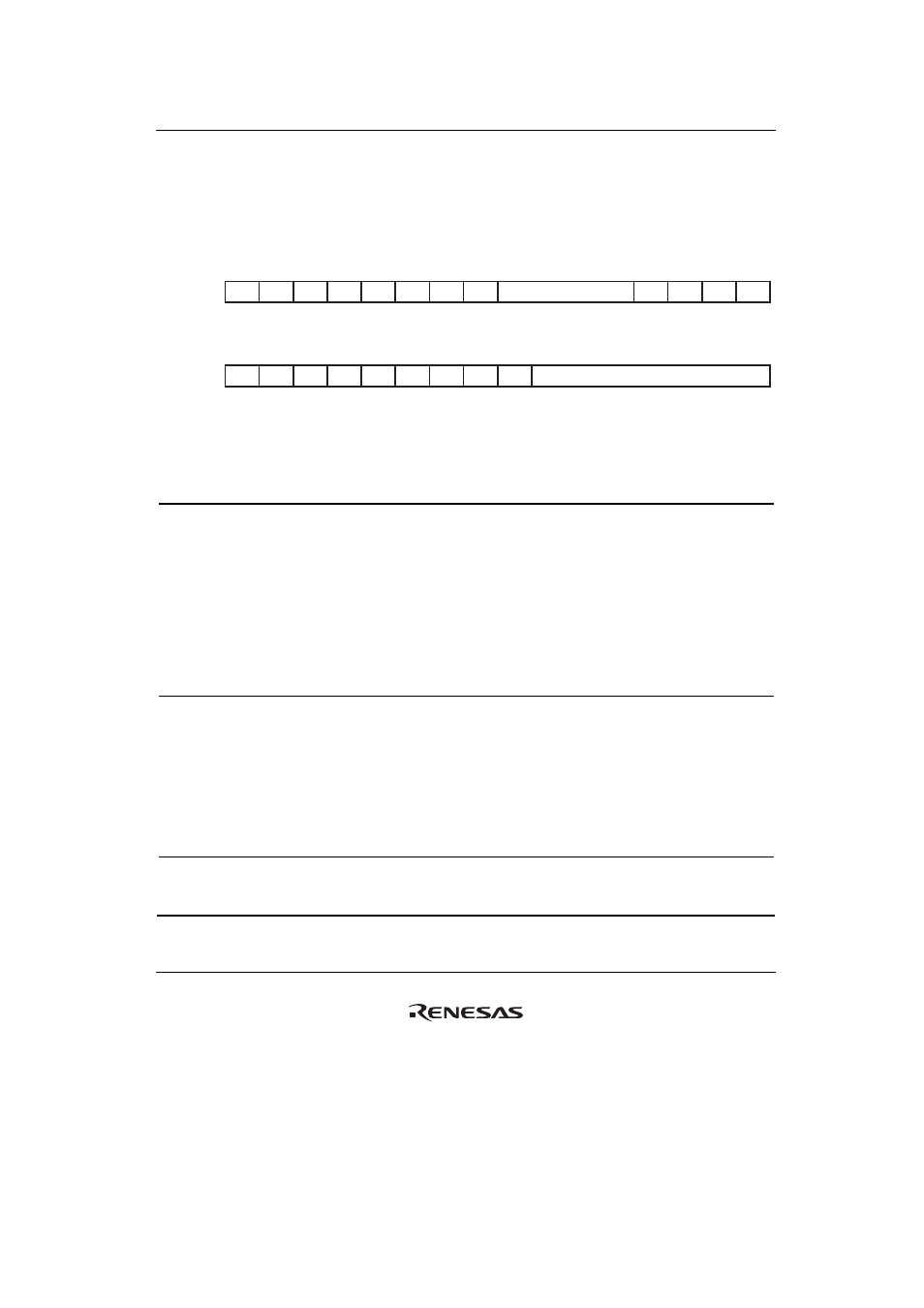
Bus Control Register (BCR)
BCR is a 32-bit readable/writable register that specifies the function, bus cycle state, etc for each
area. BCR is initialized to H'0000 0000 in big endian mode and to H'8000 0000 in little endian
mode by a power-on reset, however, not initialized by a manual reset.
16
17
18
19
20
21
22
23
24
25
26
27
28
29
31
30
0
0
0
0
0
0
0
0
0
0
0
0
0
0
x*
x*
DMA
BST
BREQ
EN
—
—
DACKBST[3:0]
OPUP
—
DPUP
—
—
—
END
IAN
MAS
TER
R/W
R/W
R
R
R/W
R/W
R/W
R/W
R/W
R
R/W
R
R
R
R
R
BIt:
Initial value:
R/W:
0
1
2
3
4
5
6
7
8
9
10
11
12
13
15
14
0
0
0
0
0
0
0
0
0
0
0
0
0
0
0
0
ASYNC[6:0]
—
—
—
—
—
—
—
—
HIZ
CNT
R/W
R/W
R/W
R/W
R/W
R/W
R/W
R
R
R
R
R
R
R
R
R/W
BIt:
Initial value:
R/W:
Note: * The initial values of bits 31 and 30 depend on the states of the external pins MODE8 and MODE9, respectively.
Bit Bit
Name
Initial
Value
R/W Description
31 ENDIAN
x
R
Endian
Flag
The value on the external pin (MODE8) that sets the
endian mode is sampled and reflected in this bit at a
power-on reset by the
PRESET pin. This bit determines
the endian for all spaces.
0: Indicates that a low level is on the MODE8 pin at a
power-on reset and the LSI has been configured for
big endian.
1: Indicates that a high level is on the MODE8 pin at a
power-on reset and the LSI has been configured for
little endian.
30 MASTER
x
R
Master/Slave
Flag
The value on the external pin (MODE9) that sets
master/slave is sampled and reflected in this bit at a
power-on reset by the
PRESET pin. This bit specifies
master/slave for all spaces.
0: Indicates that a high level is on the MODE9 and the
LSI has been configured as master.
1: Indicates that a high level is on the MODE9 and the
LSI has been configured as slave.
29 to 27
⎯
All 0
R
Reserved
These bits are always read as 0. The write value should
always be 0.