7 flags and interrupt timing, 8 low-power consumption and clock synchronization – Renesas SH7781 User Manual
Page 1200
23. Serial Peripheral Interface (HSPI)
Rev.1.00 Jan. 10, 2008 Page 1170 of 1658
REJ09B0261-0100
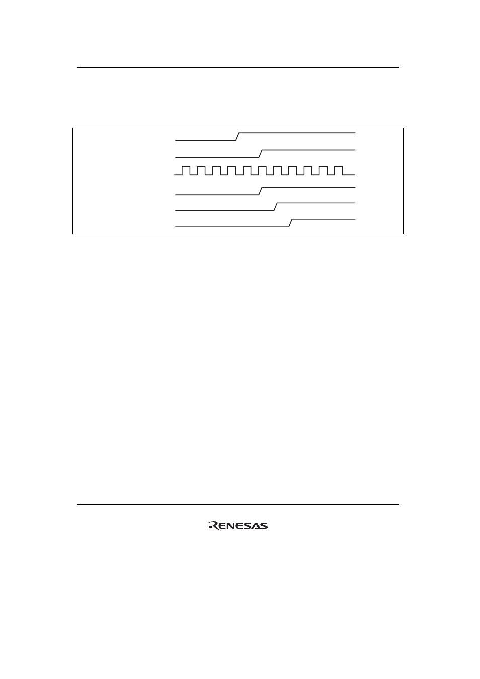
23.4.7
Flags and Interrupt Timing
The interrupt timing when the flags of the status register (SPSR) and the system control register
(SPSCR) are set is shown in figure 23.7.
HSPI_CLK
HSPI_CS
Pck
Internal interrupt
Flags (SPSR)
Interrupt
Figure 23.7 Flags and Interrupt Timing
If an interrupt cause (receive FIFO halfway, etc.) occurs, it is reflected to the status register
(SPSR) in synchronization with Pck, and an interrupt occurs.
23.4.8
Low-Power Consumption and Clock Synchronization
The HSPI operates in synchronization with the bus clock. Module standby mode is
enabled/disabled by the MSTP2 bit of the CPG module standby control register 0 (MSTPCR0).
Take the following steps to enter module standby mode.
1. Check that all data transfers have been completed. The transmit buffer (or FIFO) must be
empty and the receive buffer (or FIFO) must be read until the receive buffer becomes empty.
2. Disable all DMA requests, interrupt requests, and FIFO mode.
3. Set the MSTP2 bit of the standby control register 0 (MSTPCR0).
To activate the HSPI, write 0 to the MSTP2 bit of the standby control register 0 (MSTPCR0).