Renesas SH7781 User Manual
Page 1349
26. Serial Sound Interface (SSI) Module
Rev.1.00 Jan. 10, 2008 Page 1319 of 1658
REJ09B0261-0100
In the case of the SSI module configured as a transmitter then each word that is written to SSITDR
is transmitted in order on the serial audio bus.
In the case of the SSI module configured as a receiver each word received on the serial audio bus
is presented for reading in order by SSIRDR.
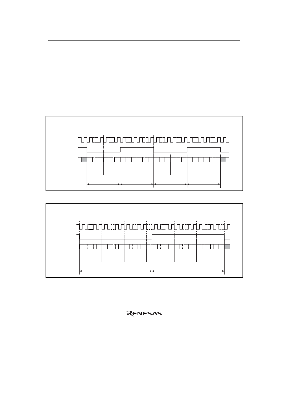
Figures 26.6 to 26.8 show how 4, 6 and 8 channels are transferred on the serial audio bus.
Note that there are no padding bits in the first example, serial data is transmitted/received first and
followed by padding bits in the second example, and padding bits are transmitted/received first
and followed by serial data in the third example. This selection is purely arbitrary.
Data
word 1
Data
word 2
Data
word 3
Data
word 4
System word 1
System word 2
Data
word 1
Data
word 2
Data
word 3
Data
word 4
System word 1
System word 2
SCKP = 0, SWSP = 0, DEL = 1, CHNL = 01, SPDP = don't care, SDTA = don't care
System word length = data word length
× 2
MSB
LSB MSB
LSB MSB
LSB MSB
LSB MSB
LSB MSB
LSB MSB
LSB MSB
LSB
LSB
MSB
SSI_SCK
SSI_WS
SSI_SDATA
Figure 26.6 Multi-channel Format (4 Channels, No Padding)
System word 2
Data
word 1
Data
word 2
Data
word 3
Paddin
g
System word 1
Data
word 4
Data
word 5
Data
word 6
Paddin
g
SCKP = 0, SWSP = 0, DEL = 1, CHNL = 10, SPDP = 1, SDTA = 0
System word length = data word length
× 3
MSB
LSB MSB
LSB MSB
LSB
MSB
MSB
LSB MSB
LSB MSB
LSB
SSI_SCK
SSI_WS
SSI_SDATA
Figure 26.7 Multi-channel Format (6 Channels with High Padding)