4 gdta operation, 1 explanation of cl operation, Figure 20.3 yuyv conversion functions – Renesas SH7781 User Manual
Page 1043
20. Graphics Data Translation Accelerator (GDTA)
Rev.1.00 Jan. 10, 2008 Page 1013 of 1658
REJ09B0261-0100
20.4
GDTA Operation
20.4.1
Explanation of CL Operation
By writing 1 to the CL_EN bit in GACER, registers in the CL register unit can be accessed. After
setting, as initial values, the input frame width/height, input padding size, output padding size,
operating mode (and, in ARGB conversion mode, the palette pointer setting), data written in
succession to CLCF is received, and upon receiving four command parameters (input Y/U/V
pointers, output pointer), processing is begun. In processing, data for one input frame as defined
by the settings (width vs. height) is read, and by setting the CL_MD bit in CLCR, YUYV
conversion or ARGB conversion is performed within the module. Processing is performed in
single frame units, and one frame's worth of converted data is transmitted to the output destination.
The CL can store two commands (in register CLCF) and does not accept the command for the next
frame when two commands are already stored (command FIFO full). A judgment as to whether
processing has ended can be made by using either an interrupt or the CL_END bit in GACISR.
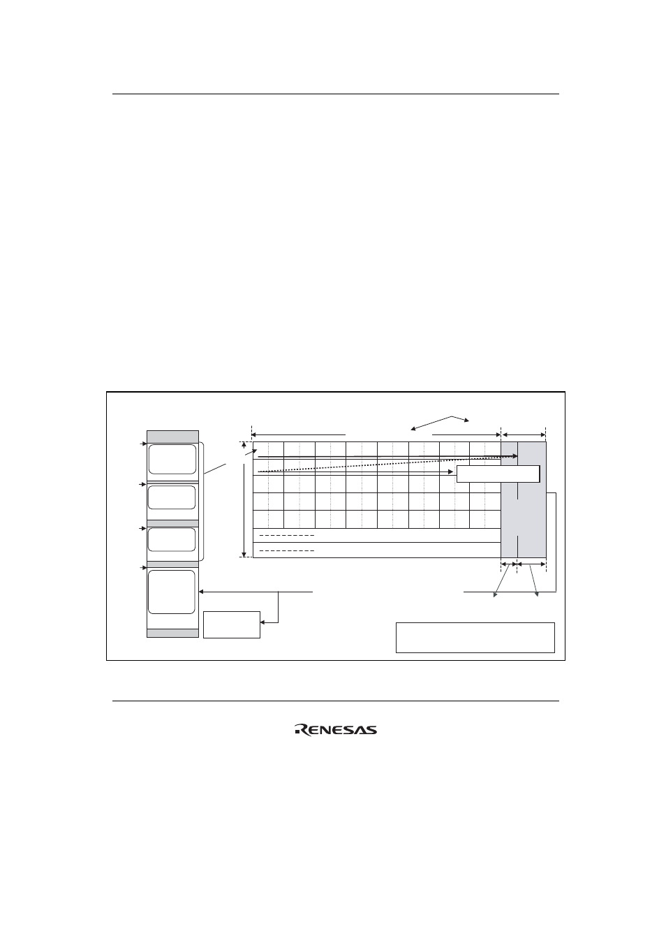
(1)
Overview of YUYV Conversion Functions
The following shows an outline of the YUYV conversion specification.
Y0 Y1
Y8 Y9
Y2 Y3
U0 U1
U4 U5
U2 U3
Y4 Y5 Y6 Y7
**
**
**
**
**
**
**
**
**
**
**
**
**
**
**
**
Input
Y pointer
Input
U pointer
Input
V pointer
Output
pointer
...
(1) Input data
reading
Frame hei
g
ht
..
.
..
.
...
V0 V1
V4 V5
V2 V3
Y0 U0 Y1 V0
Y8 U0
Y10 U1
Y9 V0
Y2 U1 Y3 V1
Y4 U2 Y5 V2
Y6 U3 Y7 V3
**
**
**
**
**
**
**
**
..
.
**
**
**
**
**
**
**
**
..
.
...
...
DDR2-SDRAM
Frame width (8 pixels in this figure)
Y0
U0
V0
Y1
Y8
U0
V0
Y9
Y16
U4
V4
Y17
Y24
U8
V8
Y25
Y32
U1
V12
Y33
Y2
U1
V1
Y3
Y10
U1
V1
Y11
Y18
U5
V5
Y19
Y26
U9
V9
Y27
Y34 U13
V13
Y35
Y4
U2
V2
Y5
Y12
U2
V2
Y13
Y20
U6
V6
Y21
Y28 U10
V10
Y29
Y36 U14
V14
Y37
Y6
U3
V3
Y7
Y14
U3
V3
Y15
Y22
U7
V7
Y23
Y30 U11
V11
Y31
Y38 U15
V15
Y39
External memory
connected to the
local bus
Display image
In the example of this figure, H'8 is set in CLIWR
and H'30 is set in CLOPR.
(2) Rearrangement (with output padding)
Output padding size (= 48 bytes)
Invalid data
Converted data output order
(3) Output data writing (including output padding data)
For output
(= 16 bytes)
Not for output
(= 32 bytes)
Depending on the specified width and padding size,
there may exist either one or neither of "padding data
for output" and "padding data not for output".
Figure 20.3 YUYV Conversion Functions