8 pci local bus basic interface – Renesas SH7781 User Manual
Page 683
13. PCI Controller (PCIC)
Rev.1.00 Jan. 10, 2008 Page 653 of 1658
REJ09B0261-0100
13.4.8
PCI Local Bus Basic Interface
The PCI interface of this LSI supports subsets in the PCI bus version 2.2 and it can be connected
to a device with a PCI bus interface. The following figures show the timing in each operating
mode.
(1)
Master Read/Write Cycle Timing
Figure 13.19 shows an example of a single-write cycle in host mode. Figure 13.20 shows an
example of a single-read cycle in host mode. Figure 13.21 shows an example of a burst-write
cycle in normal mode. Figure 13.22 is an example of a burst-read cycle in normal mode. Note that
the response speed of
DEVSEL and TRDY differs according to the connected target device. In
PIO transfer, a single read/write cycle should be used. The configuration transfers can be issued
only in host mode.
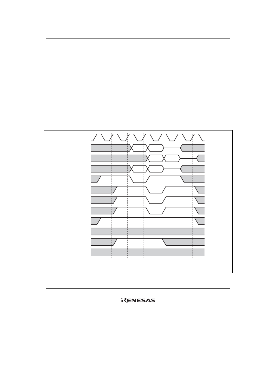
PCICLK
AD[31:0]
PAR
C/
BE[3:0]
PCIFRAME
IRDY
DEVSEL
TRDY
IDSEL
REQ
GNT
Addr
D0
AP
DP0
Com BE0
Legend:
Addr: PCI space address
Dn: nth data
AP: Address parity
DPn: nth data parity
Com: Command
LOCK
BEn: nth data byte enable
Figure 13.19 Master Write Cycle in Host Mode (Single)