2 display mode register (dsmr) – Renesas SH7781 User Manual
Page 875
19. Display Unit (DU)
Rev.1.00 Jan. 10, 2008 Page 845 of 1658
REJ09B0261-0100
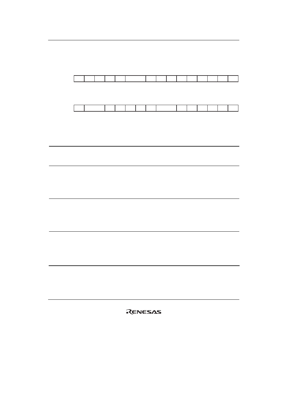
19.3.2
Display Mode Register (DSMR)
The display mode register (DSMR) sets the display operation of the display unit.
R/W:
Internal update:
R/W:
Internal update:
16
17
18
19
20
21
22
23
24
25
26
27
28
29
31
30
Bit:
Initial value:
R/W
R/W
R/W
R/W
R
R
R
R
R/W
R/W
R/W
R/W
R/W
R
R
R
*
*
*
*
*
*
*
*
*
0
0
0
0
0
0
0
0
0
0
0
0
0
0
0
0
DDIS
HSL
VSL
DIL
—
—
—
—
CSPM
DIPM
ODPM
VSPM
—
—
—
R
R
R
R
R
R
R/W
R/W
R/W
R
R
R
R/W
R/W
R/W
R/W
*
*
*
*
*
0
0
0
0
0
0
0
0
0
0
0
0
0
0
0
0
—
—
—
—
—
—
CSY
ODEV
—
—
—
CDED
CDEL
CDEM
0
1
2
3
4
5
6
7
8
9
10
11
12
13
15
14
Bit:
Initial value:
Bit Bit
Name
Initial
Value R/W
Internal
Update Description
31 to 29
⎯ All
0
R
⎯ Reserved
These bits are always read as 0. The write value
should always be 0.
28 VSPM
0 R/W
*
VSYNC Pin Mode
Settings in DSYSR are given priority over
settings in this register.
0: VSYNC signal is output to the
VSYNC pin
1: CSYNC signal is output to the
VSYNC pin
27 ODPM
0 R/W
*
ODDF Pin Mode
0: ODDF signal is output to the ODDF pin
1: CLAMP signal is output to the ODDF pin
The ODDF pin is an output pin even when the
TVM bit in DSYSR is set to TV sync mode.
26, 25
DIPM
00
R/W
*
DISP Pin Mode
00: DISP signal is output to the DISP pin
01: CSYNC signal is output to the DISP pin
10: Setting prohibited
11: DE signal is output to the DISP pin