4 timer control registers (tcrn) (n = 0 to 5), Tcr2 – Renesas SH7781 User Manual
Page 837
18. Timer Unit (TMU)
Rev.1.00 Jan. 10, 2008 Page 807 of 1658
REJ09B0261-0100
18.3.4
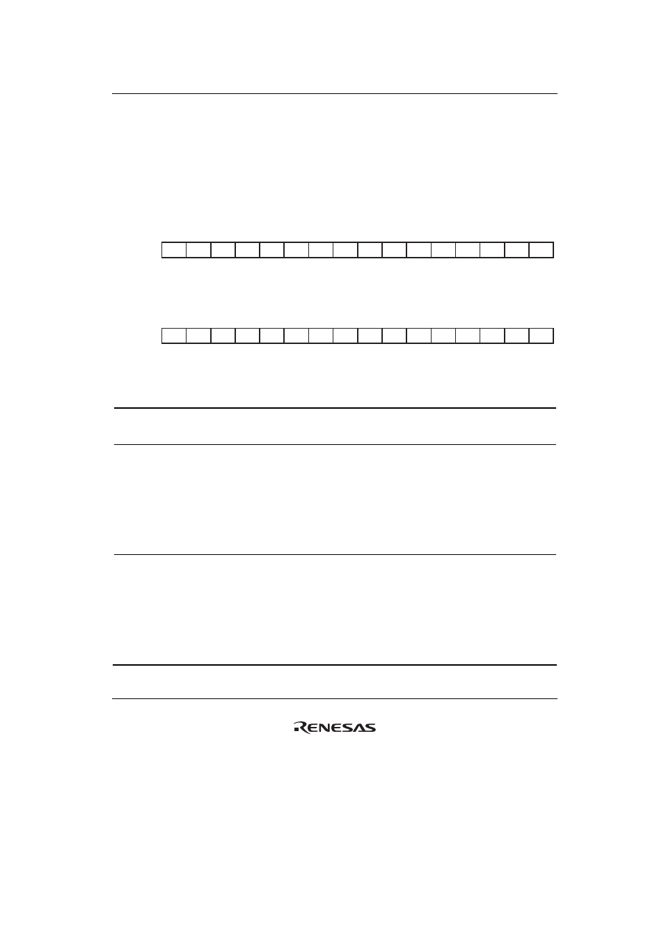
Timer Control Registers (TCRn) (n = 0 to 5)
The TCR registers are 16-bit readable/writable registers. Each TCR selects the count clock,
specifies the edge when an external clock is selected, and controls interrupt generation when the
flag indicating TCNT underflow is set to 1. TCR2 is also used for input capture control and
control of interrupt generation in the event of input capture.
• TCR0, TCR1, TCR3, TCR4 and TCR5
0
1
2
3
4
5
6
7
8
9
10
11
12
13
15
14
0
0
0
0
0
0
0
0
0
0
0
0
0
0
0
0
TPSC0
TPSC1
TPSC2
CKEG0
CKEG1
UNIE
—
—
UNF
—
—
—
—
—
—
—
R/W
R/W
R/W
R/W
R/W
R/W
R
R
R/W
R
R
R
R
R
R
R
BIt:
Initial value:
R/W:
• TCR2
0
1
2
3
4
5
6
7
8
9
10
11
12
13
15
14
0
0
0
0
0
0
0
0
0
0
0
0
0
0
0
0
TPSC0
TPSC1
TPSC2
CKEG0
CKEG1
UNIE
ICPE0
ICPE1
UNF
ICPF
—
—
—
—
—
—
R/W
R/W
R/W
R/W
R/W
R/W
R/W
R/W
R/W
R/W
R
R
R
R
R
R
BIt:
Initial value:
R/W:
Bit Bit
Name
Initial
Value
R/W Description
15 to 10 —
All 0
R
Reserved
These bits are always read as 0. The write value should
always be 0.
9 ICPF*
1
0
R/W
Input Capture Interrupt Flag
Status flag, provided in channel 2 only, which indicates
the occurrence of input capture.
0: Input capture has not occurred
[Clearing condition]
When 0 is written to ICPF
1: Input capture has occurred
[Setting condition]
When input capture occurs*
2
8 UNF 0 R/W
Underflow
Flag
Status flag that indicates the occurrence of TCNT
underflow.
0: TCNT has not underflowed
[Clearing condition]
When 0 is written to UNF
1: TCNT has underflowed
[Setting condition]
When TCNT underflows*
2