Figure 21.17 sample serial transmission flowchart – Renesas SH7781 User Manual
Page 1118
21. Serial Communication Interface with FIFO (SCIF)
Rev.1.00 Jan. 10, 2008 Page 1088 of 1658
REJ09B0261-0100
(4)
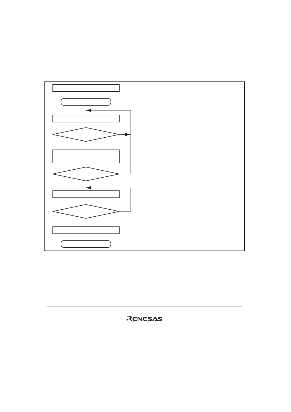
Serial Data Transmission (Clocked Synchronous Mode)
Figure 21.17 shows a sample flowchart for serial transmission.
Use the following procedure for serial data transmission after enabling the SCIF for transmission.
Start of transmission
Initialization
Read TDFE bit in SCFSR
TDFE = 1 ?
All data transmitted?
Read TEND flag in SCFSR
TEND = 1 ?
Clear TE bit in SCSCR to 0
End of transmission
[1] SCIF initialization:
See Sample SCIF Initialization Flowchart in figure
21.16.
[2] SCIF status check and transmit data write:
Read SCFSR and check that the TDFE flag is set to
1, then write transmit data to SCFTDR, and clear
the TDFE flag to 0. The transition of the TDFE flag
from 0 to 1 can also be identified by a TXI interrupt.
[3] Serial transmission continuation procedure:
To continue serial transmission, read 1 from the
TDFE flag to confirm that writing is possible, then
write data to SCFTDR, and then clear the TDFE
flag to 0.
[1]
[2]
[3]
Yes
No
No
No
Yes
Yes
Write transmit data to SCFTDR and clear
TDFE and TEND bits in SCFSR to 0
Figure 21.17 Sample Serial Transmission Flowchart