3 usage example, 1 port output function – Renesas SH7781 User Manual
Page 1479
28. General Purpose I/O Ports (GPIO)
Rev.1.00 Jan. 10, 2008 Page 1449 of 1658
REJ09B0261-0100
28.3
Usage Example
Setting procedure examples are described below.
28.3.1
Port Output Function
To output the data of port data registers (PADR to PRDR) from the GPIO output port, write B'01
to the corresponding two bits in port control registers (PACR to PRCR).
In this case, for each output port, the settings of the port pull-up control registers (PEPUPR,
PHPUPR, PJPUPR, PKPUPR, PLPUPR, PMPUPR, and PNPUPR), peripheral module select
register 1 (P1MSELR), peripheral module select register 2 (P2MSELR), and bus mode pin
(MODE11 and MODE12) are invalid.
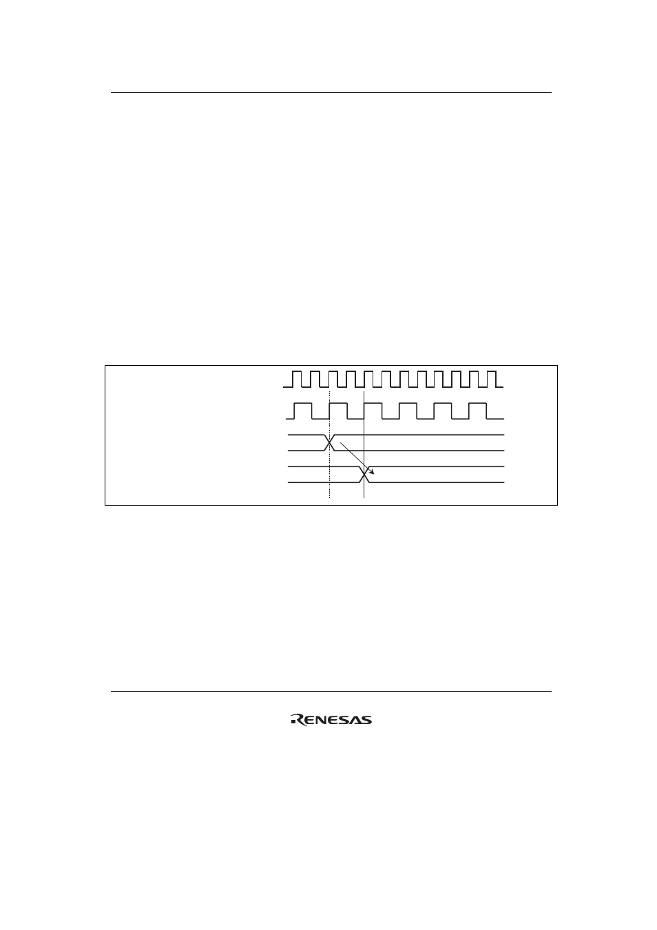
Figure 28.1 shows an example of operation timing diagram when port A is used as an output port.
The output data is written to port data registers (PADR to PRDR) and then the data is output via
the corresponding port pins after one peripheral clock (Pck).
CLKOUT
Peripheral clock (Pck)
Port A data register
PA7 to PA0
(D63/AD31 to D56/AD24)
Data
Data
Figure 28.1 Port A Data Output Timing Diagram