Renesas SH7781 User Manual
Page 1351
26. Serial Sound Interface (SSI) Module
Rev.1.00 Jan. 10, 2008 Page 1321 of 1658
REJ09B0261-0100
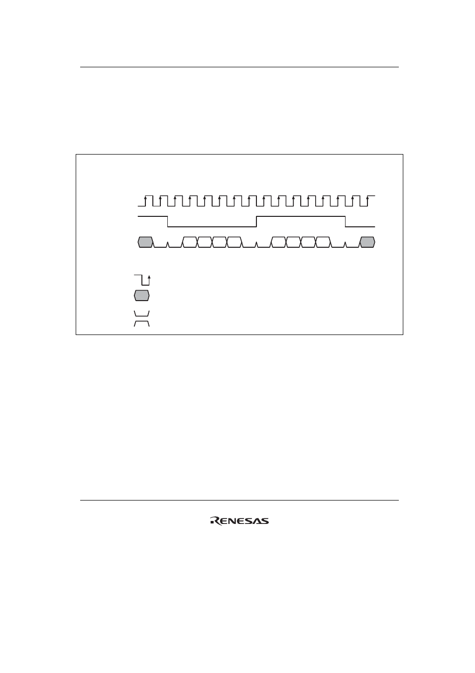
(7)
Configuration Fields—Signal Format Fields
There are several more configuration bits in non-compressed mode which will now be
demonstrated. These bits are NOT mutually exclusive, however some configurations will probably
not be useful for any other device.
They are demonstrated by referring to the following basic sample format shown in figure 26.9.
Key for this and following diagrams:
means a low level on the serial bus (padding or mute)
means a high level on the serial bus (padding)
Arrow head indicates sampling point of receiver
Bit n in SSITDR
1st channel
2nd channel
SWL = 6 bits (not attainable in SSI module, demonstration only)
DWL = 4 bits (not attainable in SSI module, demonstration only)
CHNL = 00, SCKP = 0, SWSP = 0, SPDP = 0, SDTA = 0, PDATA = 0, DEL = 0, MUEN = 0
4-bit data samples continuously written to SSITDR are transmitted onto the serial audio bus.
0
0
0
0
0
0
0
1
TDn
TD28
TD31
TD31 TD30 TD29 TD28
TD31 TD30 TD29 TD28
SSI_SCK
SSI_WS
SSI_SDATA
Figure 26.9 Basic Sample Format
(Transmit Mode with Example System/Data Word Length)
In figure 26.9, system word length of 6 bits and a data word length of 4 bits are used. Neither of
these are possible with the SSI module but are used only for clarification of the other
configuration bits.