28 color detection register (cder) – Renesas SH7781 User Manual
Page 921
19. Display Unit (DU)
Rev.1.00 Jan. 10, 2008 Page 891 of 1658
REJ09B0261-0100
19.3.28
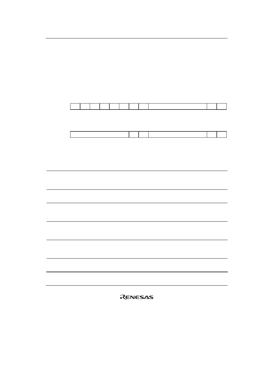
Color Detection Register (CDER)
The color detection register (CDER) sets the color for color detection.
When the display output data match the settings of this register, high level is output from the CDE
pin. For information on the output color data format, please refer to section 19.4.6, Output Data
Format.
The value is held during power-on reset and manual reset.
R/W:
Internal update:
R/W:
Internal update:
Bit:
Initial value:
Bit:
Initial value:
16
17
18
19
20
21
22
23
24
25
26
27
28
29
31
30
R
R
R/W
R/W
R/W
R/W
R/W
R/W
R
R
R
R
R
R
R
R
O
O
O
O
O
O
0
0
—
—
—
—
—
—
0
0
0
0
0
0
0
0
—
—
CDR
—
—
—
—
—
—
—
—
R
R
R/W
R/W
R/W
R/W
R/W
R/W
R
R
R/W
R/W
R/W
R/W
R/W
R/W
O
O
O
O
O
O
O
O
O
O
O
O
0
0
—
—
—
—
—
—
0
0
—
—
—
—
—
—
—
—
CDB
—
—
CDG
0
1
2
3
4
5
6
7
8
9
10
11
12
13
15
14
Bit Bit
Name
Initial
Value R/W
Internal
Update Description
31 to 24
⎯ All
0
R
⎯ Reserved
These bits are always read as 0. The write value
should always be 0.
23 to 18 CDR
Undefined R/W
Yes
Color Detection Red
Red-color data for color detection should be set.
17, 16
⎯ All
0
R
⎯ Reserved
These bits are always read as 0. The write value
should always be 0.
15 to 10 CDG
Undefined R/W
Yes
Color Detection Green
Green-color data for color detection should be
set.
9, 8
⎯ All
0
R
⎯ Reserved
These bits are always read as 0. The write value
should always be 0.
7 to 2
CDB
Undefined R/W
Yes
Color Detection Blue
Blue-color data for color detection should be set.