Renesas SH7781 User Manual
Page 310
10. Interrupt Controller (INTC)
Rev.1.00 Jan. 10, 2008 Page 280 of 1658
REJ09B0261-0100
(2)
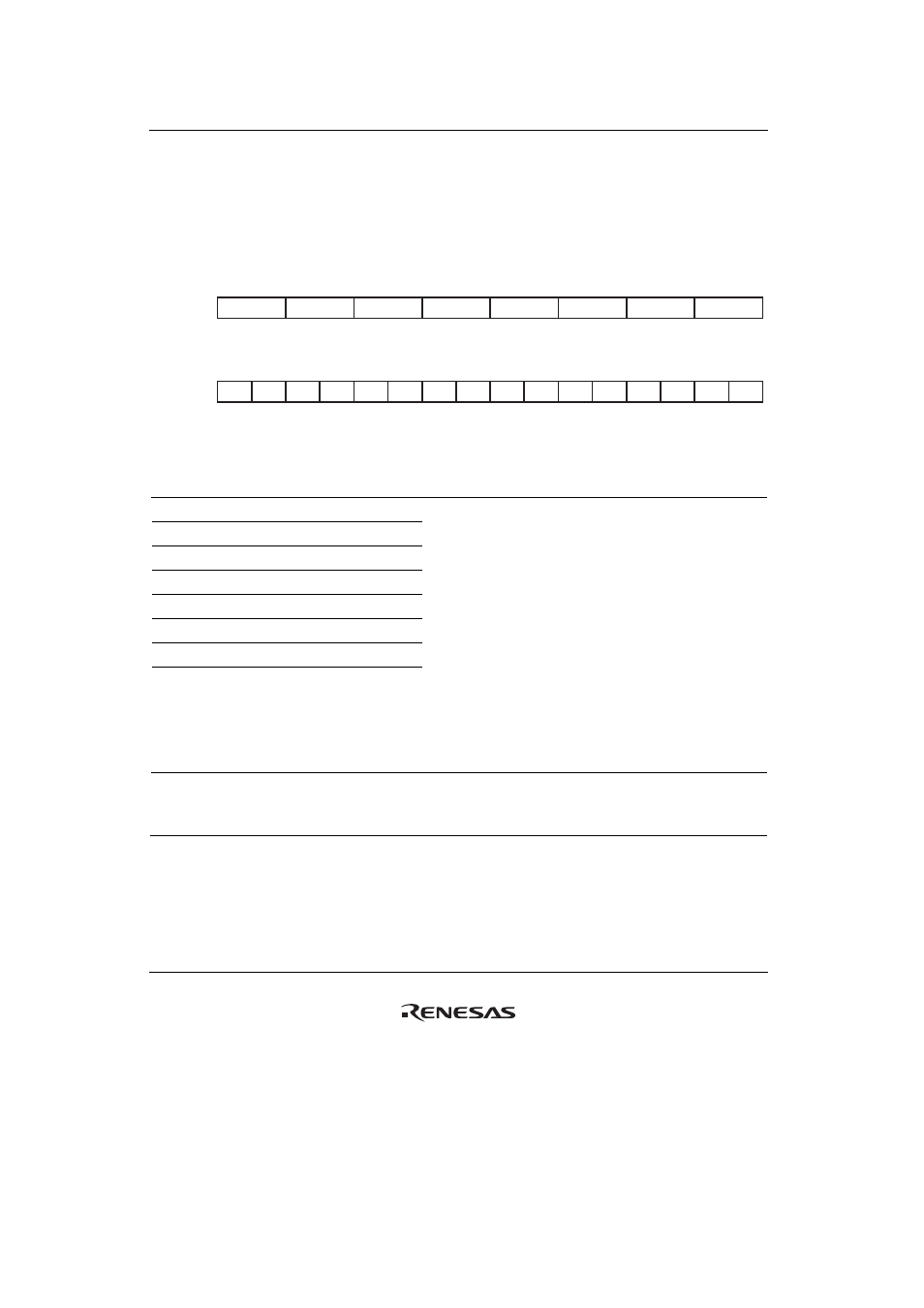
Interrupt Control Register 1 (ICR1)
ICR1 is a 32-bit readable/writable register that specifies the individual input signal detection
modes for the respective external interrupt input pins IRQ/
IRL7 to IRQ/IRL0. These settings are
only valid when IRLM0 or IRLM1 of ICR0 is set to 1 so that IRQ/
IRL3 to IRQ/IRL0 or
IRQ/
IRL7 to IRQ/IRL4 pins are used as individual interrupts (IRQ7 to IRQ0 interrupts) inputs.
16
17
18
19
20
21
22
23
24
25
26
27
28
29
31
30
0
0
0
0
0
0
0
0
0
0
0
0
0
0
0
0
IRQ7S
IRQ6S
IRQ5S
IRQ4S
IRQ3S
IRQ2S
IRQ0S
IRQ1S
R/W
R/W
R/W
R/W
R/W
R/W
R/W
R/W
R/W
R/W
R/W
R/W
R/W
R/W
R/W
R/W
Bit:
Initial value:
R/W:
0
1
2
3
4
5
6
7
8
9
10
11
12
13
15
14
0
0
0
0
0
0
0
0
0
0
0
0
0
0
0
0
⎯
⎯
⎯
⎯
⎯
⎯
⎯
⎯
⎯
⎯
⎯
⎯
⎯
⎯
⎯
⎯
R
R
R
R
R
R
R
R
R
R
R
R
R
R
R
R
Bit:
Initial value:
R/W:
Bit Name
Initial
Value R/W Description
31, 30
IRQ0S
00
R/W
29, 28
IRQ1S
00
R/W
27, 26
IRQ2S
00
R/W
25, 24
IRQ3S
00
R/W
23, 22
IRQ4S
00
R/W
21, 20
IRQ5S
00
R/W
19, 18
IRQ6S
00
R/W
17, 16
IRQ7S
00
R/W
IRQn Sense Select
Selects whether the corresponding individual pin
interrupt signal on the IRQ/IRL7 to IRQ/IRL0 pins is
detected on rising or falling edges, or at the high or
low level.
00: The interrupt request is detected on falling edges
of the IRQn input.
01: The interrupt request is detected on rising edges
of the IRQn input.
10: The interrupt request is detected when the IRQn
input is at the low level.
11: The interrupt request is detected when the IRQn
input is at the high level.
Note: n = 0 to 7
15 to 0
⎯ All
0
R
Reserved
These bits are always read as 0. The write value
should always be 0.
Notes: 1. When an IRQ pin is set for level input (IRQnS1 = 1) and the source holding mode
(LVLMODE of ICR0) of the interrupt control register 0 (ICR0) is 0, the interrupt source is
held until the CPU accepts the interrupt (this is also true for other interrupts). Therefore,
even if an interrupt source is disabled before this LSI returns from sleep mode,
branching of processing to the interrupt handler when this LSI returns from sleep mode
is guaranteed. A held interrupt can be cleared by setting the corresponding interrupt
mask bit (the IM bit in the interrupt mask register) to 1 (refer to section 10.7.3, Clearing