Figure 20.7 mc processing procedure – Renesas SH7781 User Manual
Page 1058
20. Graphics Data Translation Accelerator (GDTA)
Rev.1.00 Jan. 10, 2008 Page 1028 of 1658
REJ09B0261-0100
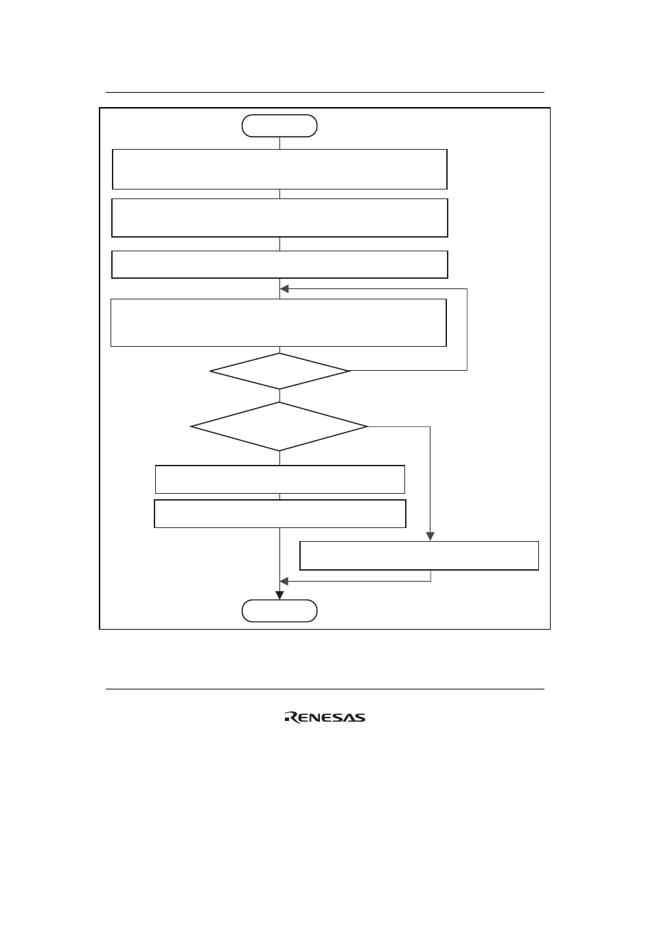
Start
End
Is an interrupt used to recognize
processing completion?
Continuous processing?
[Step (1) Clear the MC access mask]
After the CPU sets the key code in GACMR within the bus interface,
set GACER to enable access to the MC function block.
[Step (2) Initialize the MC function block]
The CPU sets the frame width/height, input Y/UV padding size, output frame Y/U/V pointers,
past frame Y/U/V pointers, and future frame Y/U/V pointers.
[Step (3) Write IDCT data to RAM 1]
The CPU writes IDCT data to RAM 1.
[Step (4) Write commands to FIFO]
The CPU writes commands to MCCF. Eight command parameters are required,
and are written in sequence.
For details of settings, refer to section 20.3.21, MC Command FIFO (MCCF).
[Step (5) Write the end command to command FIFO]
The CPU writes the end command to MCCF.
[Step (7) Check the register to confirm processing completion]
Processing completion is judged using the MC_END bit in GACISR.
[Step (6) Wait for an interrupt signaling processing completion]
Processing completion is judged using an interrupt from the CPU.
No
No
Yes
Yes
Figure 20.7 MC Processing Procedure