NETGEAR M4350-24F4V 24-Port 10G SFP+ Managed AV Network Switch User Manual
Page 926

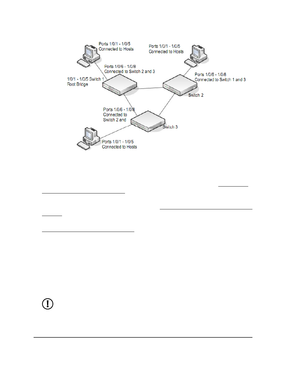
Figure 2. MSTP sample configuration
Perform the following procedures on each switch to configure MSTP:
1. Use the VLAN Configuration page to create VLANs 300 and 500 (see Change the
internal VLAN allocation settings on page 233).
2. On the VLAN Membership page, include ports 1 through 8 as tagged (T) or untagged
(U) members of VLAN 300 and VLAN 500 (see Change the internal VLAN allocation
settings on page 233).
3. On the STP Configuration page, enable the Spanning Tree State option (see
Configure the CST interface settings on page 284).
Use the default values for the rest of the STP configuration settings. By default, the
STP operation mode is MSTP and the configuration name is the switch MAC address.
4. On the CST Configuration page, set the bridge priority value for each of the three
switches to force Switch 1 to be the root bridge:
•
Switch 1: 4096
•
Switch 2: 12288
•
Switch 3: 20480
NOTE: Bridge priority values are multiples of 4096.
Main User Manual
926
Configuration Examples
Fully Managed Switches M4350 Series Main User Manual
