NETGEAR AV Line M4250 GSM4210PX 8-Port Gigabit PoE+ Compliant Managed AV Switch with SFP (220W) User Manual
Page 781
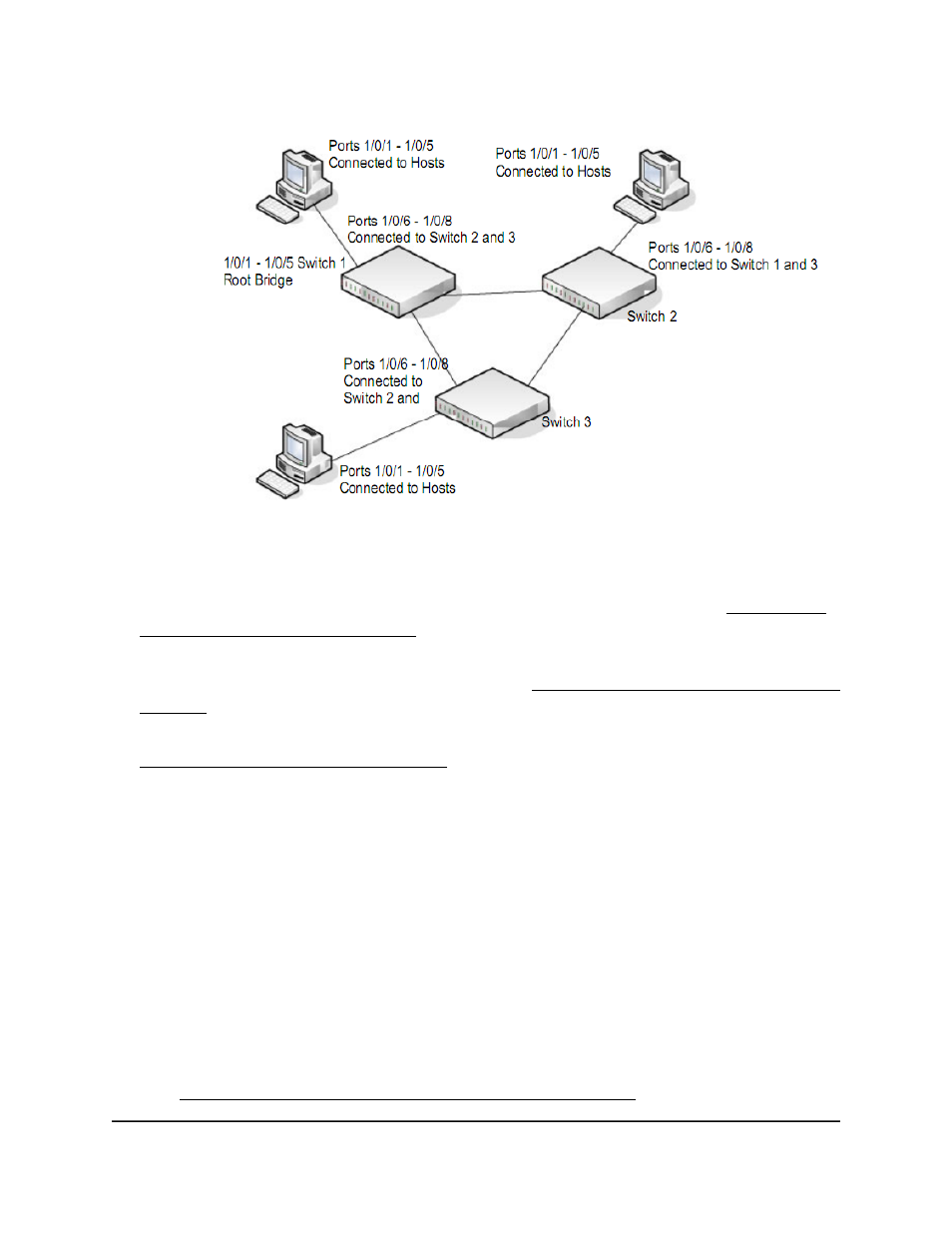
Figure 2. MSTP sample configuration
Perform the following procedures on each switch to configure MSTP:
1. Use the VLAN Configuration page to create VLANs 300 and 500 (see Change the
internal VLAN allocation settings on page 193).
2. On the VLAN Membership page, include ports 1 through 8 as tagged (T) or untagged
(U) members of VLAN 300 and VLAN 500 (see Change the internal VLAN allocation
settings on page 193).
3. On the STP Configuration page, enable the Spanning Tree State option (see
Configure the CST interface settings on page 231).
Use the default values for the rest of the STP configuration settings. By default, the
STP operation mode is MSTP and the configuration name is the switch MAC address.
4. On the CST Configuration page, set the bridge priority value for each of the three
switches to force Switch 1 to be the root bridge:
• Switch 1: 4096
• Switch 2: 12288
• Switch 3: 20480
Note: Bridge priority values are multiples of 4096.
If you do not specify a root bridge and all switches are assigned the same bridge
priority value, the switch with the lowest MAC address is elected as the root bridge
(see Configure the CST settings and display the CST status on page 229).
Main User Manual
781
Configuration Examples
AV Line of Fully Managed Switches M4250 Series Main User Manual