Altera Transceiver PHY IP Core User Manual
Page 286
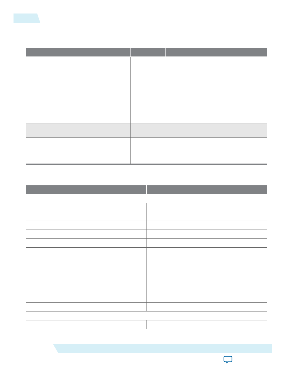
Table 11-11: Avalon-ST RX Interface
The following table describes the signals in the Avalon-ST output interface. These signals are driven from the PCS
to the MAC. This is an Avalon source interface.
Signal Name
Direction
Description
rx_parallel_data [(<n><d>)-1:0]
Output
This is RX parallel data driven from the
Deterministic Latency PHY IP Core. The
ready latency on this interface is 0, so that
the MAC must be able to accept data as
soon as the PHY comes out of reset. Data
driven from this interface is always valid.
Refer to the following "Signal Definitions
for rx_parallel_data with and without 8B/
10B Encoding" table for the signals that
correspond to data, control, and status
signals.
rx_clkout[
Output
This is the clock for the RX parallel data
source interface.
rx_datak[(
Output
Data and control indicator for the source
data. When 0, indicates that
rx_parallel_
data
is data, when 1, indicates that
rx_
parallel_data
is control.
Table 11-12: Signal Definitions for rx_parallel_data with and without 8B/10B Encoding
This table shows the signals within rx_parallel_data that correspond to data, control, and status signals.
RX Data Word
Description
Signal Definitions with 8B/10B Enabled
rx_parallel_data[7:0]
RX data bus
rx_parallel_data[8]
RX data control character
rx_parallel_data[9]
Error Detect
rx_parallel_data[10]
Word Aligner / synchronization status
rx_parallel_data[11]
Disparity error
rx_parallel_data[12]
Pattern detect
rx_parallel_data[14:13]
FIFO status. The following encodings are defined:
• 2’b00: Normal data
• 2’b01: Deletion
• 2’b10: Insertion (or Underflow with 9’h1FE or
9’h1F7)
• 2’b11: Overflow
rx_parallel_data[15]
Running disparity value
Signal Definitions with 8B/10B Disabled
rx_parallel_data[9:0]
RX data bus
11-18
Data Interfaces for Deterministic Latency PHY
UG-01080
2015.01.19
Altera Corporation
Deterministic Latency PHY IP Core