Figure 30-51. aal1 txbd, Table 30-39. aal1 txbd field descriptions, 12 aal0 txbds – Freescale Semiconductor MPC8260 User Manual
Page 998: Aal0 txbds -78, Aal1 txbd -78, Aal1 txbd field descriptions -78
ATM Controller and AAL0, AAL1, and AAL5
MPC8260 PowerQUICC II Family Reference Manual, Rev. 2
30-78
Freescale Semiconductor
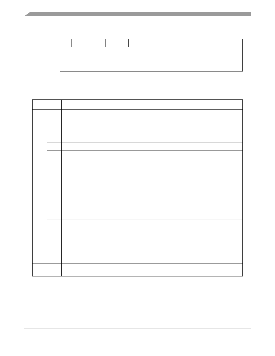
30.10.5.12 AAL0 TxBDs
shows AAL0 TxBDs. Note that the data length field is calculated internally as 52 bytes, plus
the extra header length (defined in FPSMR[TEHS]) when in UDC mode.
0
1
2
3
4
5
6
7
8
9
10
11
12
13
14
15
Offset + 0x00
R
—
W
I
—
CM
—
Offset + 0x02
Data Length (DL)
Offset + 0x04
Tx Data Buffer Pointer (TXDBPTR)
Offset + 0x06
Figure 30-51. AAL1 TxBD
Table 30-39. AAL1 TxBD Field Descriptions
Offset
Bits
Name
Description
0x00
0
R
Ready
0 The buffer associated with this BD is not ready for transmission. The user is free to
manipulate this BD or its associated buffer. The CP clears this bit after the buffer has
been sent or after an error condition is encountered.
1 The buffer prepared for transmission by the user has not been sent or is being sent.
No fields of this BD may be written by the user once R is set.
1
—
Reserved, should be cleared.
2
W
Wrap (final BD in table)
0 Not the last BD in the TxBD table.
1 Last BD in the TxBD table. After this buffer is used, the CP sends outgoing data from
the first BD in the table (the BD pointed to by the channel’s TCT[TBD_BASE]). The
number of TxBDs in this table is determined only by the W bit. The current table cannot
exceed 64 Kbytes.
3
I
Interrupt
0 No interrupt is generated after this buffer has been serviced.
1 A Tx buffer event is sent to the interrupt queue after this buffer is serviced.
FCCE[GINT
x
] is set when the INT_CNT counter reaches the global interrupt
threshold.
4–5
—
Reserved, should be cleared.
6
CM
Continuous mode
0 Normal operation.
1 The CP does not clear the ready bit after this BD is closed, allowing the associated
buffer to be retransmitted automatically when the CP next accesses this BD.
7–11
—
Reserved, should be cleared.
0x02
—
DL
The number of octets the ATM controller should transmit from this BD’s buffer. It is not
modified by the CP. The value of DL should be greater than zero.
0x04
—
TXDBPTR Tx data buffer pointer. Points to the address of the associated buffer. The buffer may
reside in either internal or external memory. This value is not modified by the CP.