Chapter 18 timers, Figure 18-1. timer block diagram, 1 features – Freescale Semiconductor MPC8260 User Manual
Page 637: Timers, Chapter 18, Features -1, Timer block diagram -1, Chapter 18, “timers
MPC8260 PowerQUICC II Family Reference Manual, Rev. 2
Freescale Semiconductor
18-1
Chapter 18
Timers
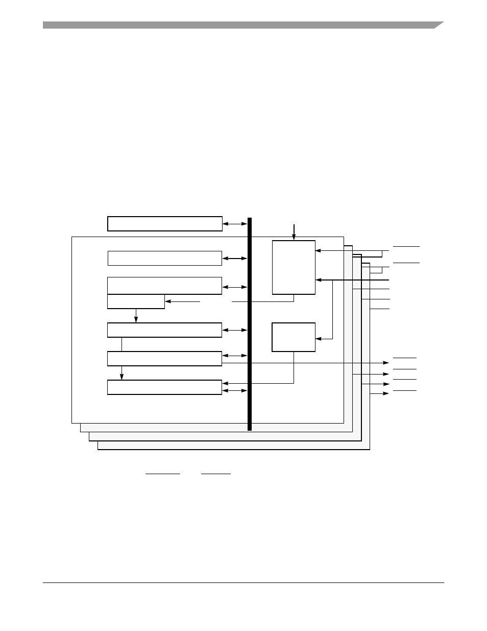
The CPM includes four identical 16-bit general-purpose timers or two 32-bit timers. Each general-purpose
timer consists of a timer mode register (TMR), a timer capture register (TCR), a timer counter (TCN), a
timer reference register (TRR), a timer event register (TER), and a timer global configuration register
(TGCR). The TMRs contain the prescaler values programmed by the user.
shows the timer block diagram.
Figure 18-1. Timer Block Diagram
Pin assignments for TINx, TGATEx, and TOUTx are described in
18.1
Features
The key features of the timer include the following:
•
The maximum input clock is the bus clock
•
Maximum period of 4 seconds (at 66 MHz)
Timer
Capture
Detection
Timer Event Register
Mode Register
Mode Bits
Prescaler
Timer Counter (TCN)
Capture Register
Reference Register
Divider
Clock
TER1
TMR1
TCN1
TRR1
TCR1
Bus
TIN1
TOUT1
Timer1
Timer2
Timer3
Timer4
Global Configuration Register
TGATE1
TGATE2
TGCR
TIN2
TIN3
TIN4
TOUT2
TOUT3
TOUT4
Clock
Clock
Generator