Freescale Semiconductor MPC8260 User Manual
Page 682
Serial Communications Controllers (SCCs)
MPC8260 PowerQUICC II Family Reference Manual, Rev. 2
20-4
Freescale Semiconductor
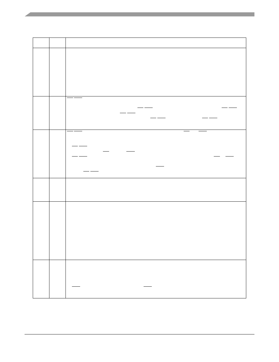
19–20
TRX,
TTX
Transparent receiver/transmitter. The receiver, transmitter, or both can use totally transparent
operation, regardless of GSMR_L[MODE]. For example, to configure the transmitter as a UART and
the receiver for totally transparent operations, set MODE = 0b0100 (UART), TTX = 0, and TRX = 1.
0 Normal operation.
1 The channel uses totally transparent mode, regardless of the protocol chosen in
GSMR_L[MODE].
For full-duplex totally transparent operation, set both TTX and TRX.
Note: An SCC cannot operate with half in Ethernet mode and half in transparent mode. That is, if
MODE = 0b1100 (Ethernet), erratic operation occurs unless TTX = TRX.
21, 22
CDP,
CTSP
CD/CTS pulse. If this SCC is used in the TSA and is programmed in transparent mode, set CTSP
and refer to
Section 24.4.2, “Synchronization and the TSA
,” for options on programming CDP.
0 Normal operation (envelope mode). CD/CTS should envelope the frame. Negating CD/CTS
during reception causes a CD/CTS lost error.
1 Pulse mode. Synchronization occurs when CD/CTS is asserted; further CD/CTS transitions do
not affect reception.
23, 24
CDS,
CTSS
CD/CTS sampling. Determine synchronization characteristics of CD and CTS. If the SCC is in
transparent mode and is used in the TSA, CDS and CTSS must be set. Also, CDS and CTSS must
be set for loopback testing in transparent mode.
0 CD/CTS is assumed to be asynchronous with data. It is internally synchronized by the SCC, then
data is received (CD) or sent (CTS) after several clock delays.
1 CD/CTS is assumed to be synchronous with data, which speeds up operation. CD or CTS must
transition while the Rx/Tx clock is low, at which time, the transfer begins. Useful for connecting
PowerQUICC II in transparent mode since the RTS of one PowerQUICC II can connect directly
to the CD/CTS of another.
25
TFL
Transmit FIFO length.
0 Normal operation. The transmit FIFO is 32 bytes.
1 The Tx FIFO is 1 byte. This option is used with character-oriented protocols, such as UART, to
ensure a minimum FIFO latency at the expense of performance.
26
RFW
Rx FIFO width.
0 Receive FIFO is 32 bits wide for maximum performance; the Rx FIFO is 32 bytes. Data is not
normally written to receive buffers until at least 32 bits are received. This configuration is required
for HDLC-type protocols and Ethernet and is recommended for high-performance transparent
protocols.
1 Low-latency operation. The receive FIFO is 8 bits wide, reducing the Rx FIFO to a quarter its
normal size. This allows data to be written to the buffer as soon as a character is received, instead
of waiting to receive 32 bits. This configuration must be chosen for character-oriented protocols,
such as UART. It can also be used for low-performance, low-latency, transparent operation.
However, it must not be used with HDLC, HDLC Bus, AppleTalk, or Ethernet because it causes
erratic behavior.
27
TXSY
Transmitter synchronized to the receiver. Intended for X.21 applications where the transmitted data
must begin an exact multiple of 8-bit periods after the received data arrives.
0 No synchronization between receiver and transmitter (default).
1 The transmit bit stream is synchronized to the receiver. Additionally, if RSYN = 1, transmission in
totally transparent mode does not occur until the receiver synchronizes with the bit stream and
CTS is asserted to the SCC. Assuming CTS is asserted, transmission begins 8 clocks after the
receiver starts receiving data.
Table 20-1. GSMR_H Field Descriptions (continued)
Bit
Name
Description