Figure 21-2. two uart multidrop configurations, 9 receiving control characters, Receiving control characters -7 – Freescale Semiconductor MPC8260 User Manual
Page 711: Two uart multidrop configurations -7, Section 21.9, Receiving control characters, Figure 21-2
SCC UART Mode
MPC8260 PowerQUICC II Family Reference Manual, Rev. 2
Freescale Semiconductor
21-7
•
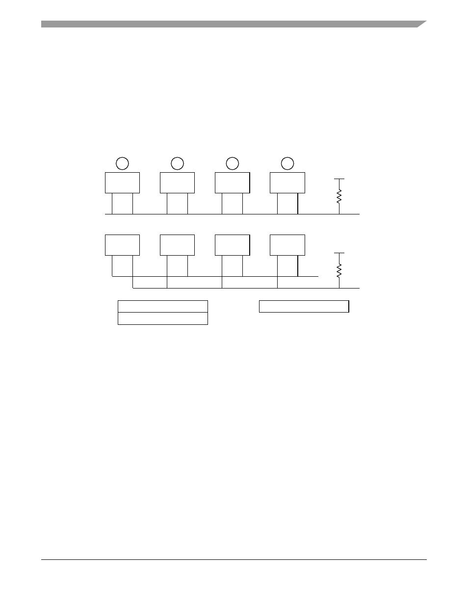
Automatic multidrop mode—The controller checks the incoming address character and accepts
subsequent data only if the address matches one of two user-defined values. The two 16-bit address
registers, UADDR1 and UADDR2, support address recognition. Only the lower 8 bits are used so
the upper 8 bits should be cleared; for addresses less than 8 bits, unused high-order bits should also
be cleared. The incoming address is checked against UADDR1 and UADDR2. When a match
occurs, RxBD[AM] indicates whether UADDR1 or UADDR2 matched.
•
Manual multidrop mode—The controller receives all characters. An address character is always
written to a new buffer and can be followed by data characters. User software performs the address
comparison.
Figure 21-2. Two UART Multidrop Configurations
21.9
Receiving Control Characters
The UART receiver can recognize special control characters used in a message-based environment. Eight
control characters can be defined in a control character table in the UART parameter RAM. Each incoming
character is compared to the table entries using a mask (the received control character mask, RCCM) to
strip don’t cares. If a match occurs, the received control character can either be written to the receive buffer
or rejected.
If the received control character is not rejected, it is written to the receive buffer. The receive buffer is then
automatically closed to allow software to handle end-of-message characters. Control characters that are
not part of the actual message, such as XOFF, can be rejected. Rejected characters bypass the receive
buffer and are written directly to the received control character register (RCCR), which triggers maskable
interrupt.
The 16-bit entries in the control character table support control character recognition. Each entry consists
of the control character, a valid bit (end of table), and a reject bit. See
.
Tx
Rx
1
Tx
Rx
2
Tx
Rx
3
Tx
Rx
4
Tx
Rx
Tx
Rx
Tx
Rx
Tx
Rx
Slave 2
Slave 3
Slave 1
Master
UADDR1
UADDR2
PAODR
Choose wired-or operation in the port A
open-drain register to allow multiple transmit
pins to be directly connected
+ V
R
Two 8-bit addresses can be automatically
recognized in either configuration
+ V
R