Spi transfer format with spmode[cp] = 0 -7, Figure 38-5 – Freescale Semiconductor MPC8260 User Manual
Page 1253
Serial Peripheral Interface (SPI)
MPC8260 PowerQUICC II Family Reference Manual, Rev. 2
Freescale Semiconductor
38-7
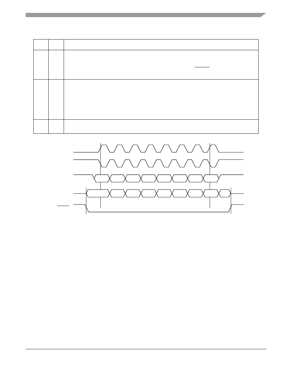
Figure 38-5. SPI Transfer Format with SPMODE[CP] = 0
shows the SPI transfer format in which SPICLK starts toggling at the beginning of the transfer
(SPMODE[CP] = 1).
7
EN
Enable SPI. Do not change other SPMODE bits when EN is set.
0 The SPI is disabled. The SPI is in a reset state and consumes minimal power. The SPI BRG is not
functioning and the input clock is disabled.
1 The SPI is enabled. Configure SPIMOSI, SPIMISO, SPICLK, and SPISEL to connect to the SPI as
described in
8–11
LEN
Character length in bits per character. If the character length is not greater than a byte, every byte in
memory holds (LEN+1) valid bits. If the character length is greater than a byte, every half-word holds
(LEN+1) valid bits. See
Section 38.4.1.1, “SPI Examples with Different SPMODE[LEN] Values
0000–0010 Reserved, causes erratic behavior.
0011 4-bit characters
…
1111 16-bit characters
12–15
PM
Prescale modulus select. Specifies the divide ratio of the prescale divider in the SPI clock generator.
BRGCLK is divided by 4 * ([PM0–PM3] + 1), a range from 4 to 64. The clock has a 50% duty cycle.
Table 38-1. SPMODE Field Descriptions (continued)
Bits
Name
Description
SPICLK
SPICLK
SPIMOSI
SPISEL
(From Master)
SPIMISO
(From Slave)
(CI = 0)
(CI = 1)
NOTE: Q = Undefined Signal.
msb
lsb
msb
Q
lsb