4 aal0 protocol-specific rct, Figure 30-29. aal0 protocol-specific rct, Aal0 protocol-specific rct -49 – Freescale Semiconductor MPC8260 User Manual
Page 969: Aal0-specific rct field descriptions -49, Section 30.10.2.2.4, “aal0 protocol-specific rct
ATM Controller and AAL0, AAL1, and AAL5
MPC8260 PowerQUICC II Family Reference Manual, Rev. 2
Freescale Semiconductor
30-49
30.10.2.2.4
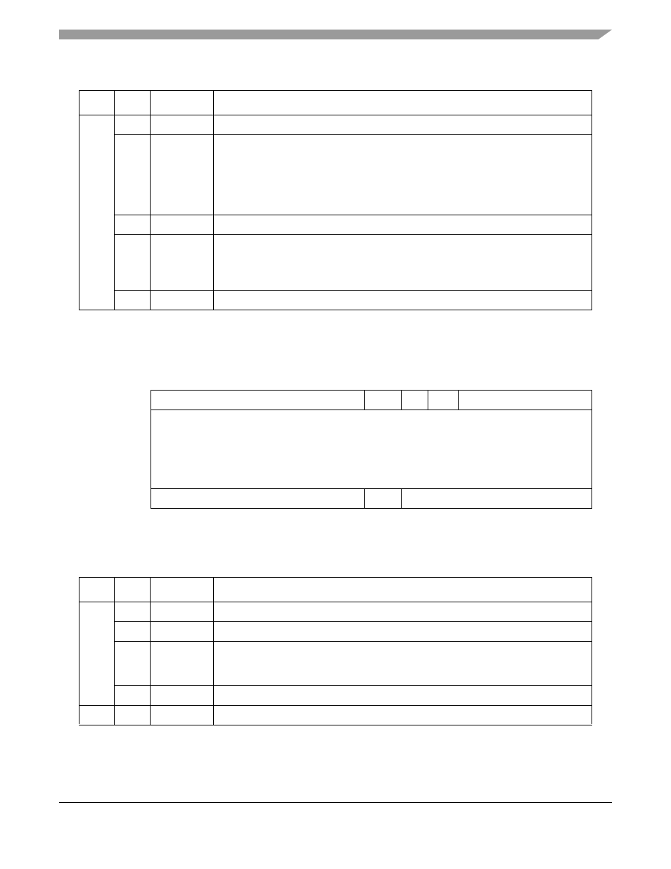
AAL0 Protocol-Specific RCT
shows the layout for the AAL0 protocol-specific RCT.
describes AAL0 protocol specific RCT fields.
0x18
0–3
—
Reserved, should be cleared.
4
SNEM
Sequence number error flag interrupt mask
0 This mode is disabled.
1 When an out-of-sequence error occurs, an RXB interrupt is sent to the interrupt
queue even if RCT[RXBM] is cleared. Note that this mode is the buffer error
reporting mechanism during automatic data forwarding (ATM-to-TDM bridging)
when no buffer processing is required (RCT[RXBM]=0).
5–7
—
Reserved, should be cleared.
8
RXBM
Receive buffer interrupt mask
0 The receive buffer event of this channel is disabled. (The event is not sent to the
interrupt queue.)
1 The receive buffer event of this channel is enabled.
9–15
—
Reserved, should be cleared.
0
1
2
3
4
5
6
7
8
9
10
11
12
13
14
15
Offset + 0x0E
—
0
1
INVE
—
Offset + 0x10
—
Offset + 0x12
Offset + 0x14
Offset + 0x16
Offset + 0x18
—
RXBM
—
Figure 30-29. AAL0 Protocol-Specific RCT
Table 30-20. AAL0-Specific RCT Field Descriptions
Offset
Bits
Name
Description
0x0E
0-7
—
Reserved, should be cleared.
8-9
0b01
Must be programmed to 0b01 for AAL0.
10
INVE
Inverted empty.
0 RxBD[E] is interpreted normally (1 = empty, 0 = not empty).
1 RxBD[E] is handled in negative logic (0 = empty, 1 = not empty).
11-15
—
Reserved, should be cleared.
0x10
—
—
Reserved, should be cleared.
Table 30-19. AAL1 Protocol-Specific RCT Field Descriptions (continued)
Offset
Bits
Name Description