Figure 22-15. delayed rts mode, 5 using the time-slot assigner (tsa), Using the time-slot assigner (tsa) -21 – Freescale Semiconductor MPC8260 User Manual
Page 749: Delayed rts mode -21, Hdlc bus tdm transmission line configuration -21
SCC HDLC Mode
MPC8260 PowerQUICC II Family Reference Manual, Rev. 2
Freescale Semiconductor
22-21
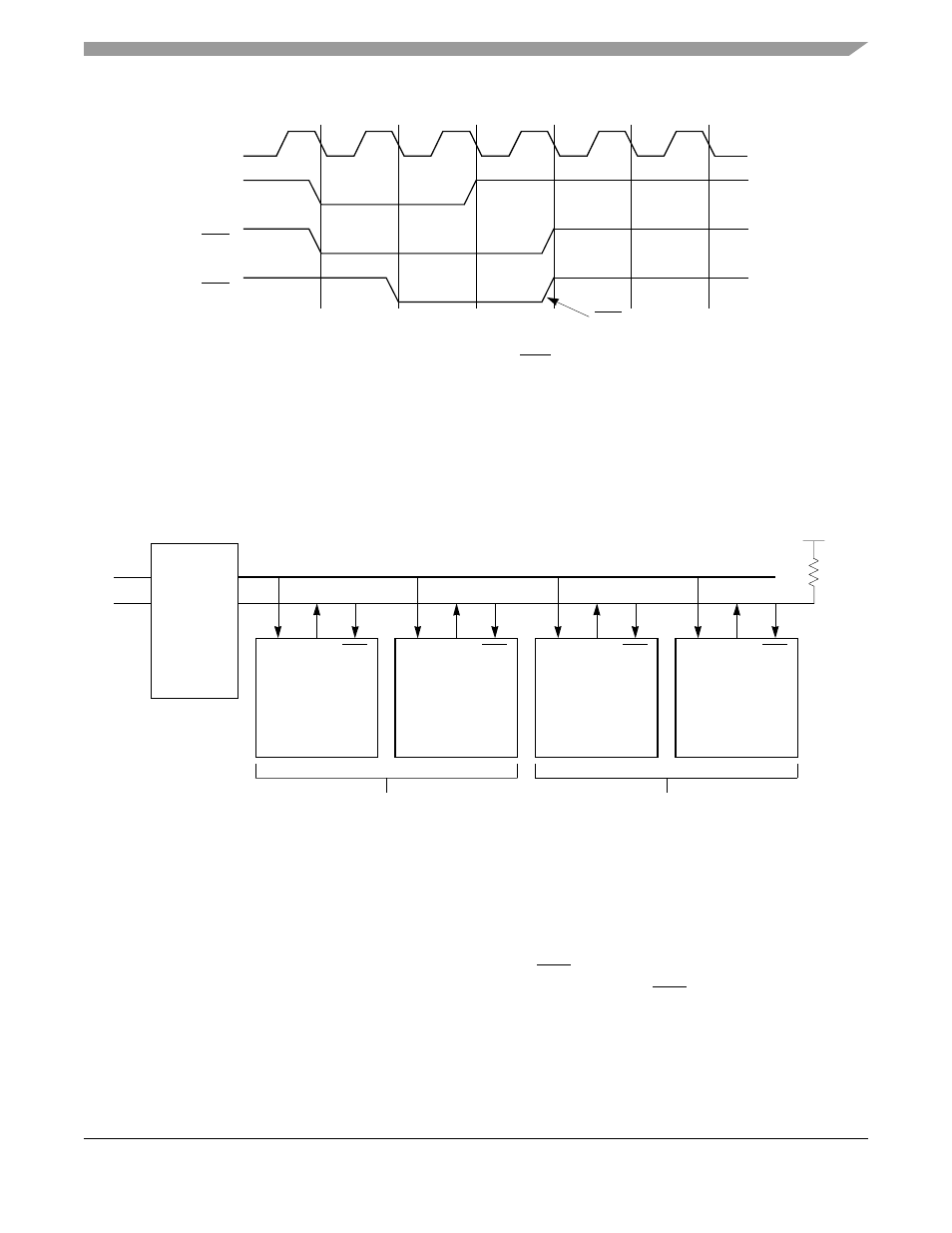
Figure 22-15. Delayed RTS Mode
22.15.5 Using the Time-Slot Assigner (TSA)
HDLC bus controllers can be used with a time-division multiplexed transmission line and a local bus, as
shown in
. Local stations use time slots to communicate over the TDM transmission line;
stations that share a time slot use the HDLC bus protocol to control access to the local bus.
Figure 22-16. HDLC Bus TDM Transmission Line Configuration
The local SCCs in HDLC bus mode communicate only with the transmission line and not with each other.
The SCCs use the TSA of the serial interface, receiving and sending data over L1TXDx and L1RXDx.
Because collisions are still detected from the individual SCC CTS pin, it must be configured to connect to
the chosen SCC. Because the SCC only receives clocks during its time slot, CTS is sampled only during
the Tx clock edges of the particular SCC time slot.
TCLK
RTS active for
only 2 bit times
TXD
CTS
RTS
1st Bit
2nd Bit
3rd Bit
Collision
Local HDLC Bus
HDLC Bus
Controller
L1RXD
CTS
L1TXD
B
HDLC Bus
Controller
L1RXD
CTS
L1TXD
D
+ 3.3 V
R
NOTES:
1. All TXD pins of slave devices should be configured to open-drain in the port C parallel I/O port.
2. The TSA in the SI of each station is used to configure the preferred time slot.
Tx
Rx
Line Driver
HDLC Bus
Controller
L1RXD
CTS
L1TXD
C
HDLC Bus
Controller
L1RXD
CTS
L1TXD
A
Stations share time-slot n
Stations share time-slot m
3. The choice of the number of stations to share a time slot is user-defined. It is two in this example.