Table 30-16. rct field descriptions (continued), Rct field descriptions -44, Table 30-16 – Freescale Semiconductor MPC8260 User Manual
Page 964
ATM Controller and AAL0, AAL1, and AAL5
MPC8260 PowerQUICC II Family Reference Manual, Rev. 2
30-44
Freescale Semiconductor
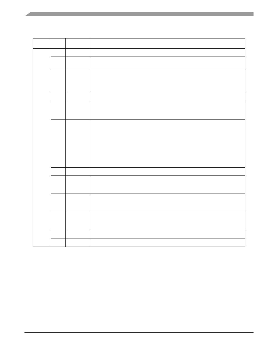
Table 30-16. RCT Field Descriptions
Offset
Bits
Name Description
0x00
0–1
—
Reserved, should be cleared.
2
GBL
Global. Asserting GBL enables snooping of data buffers, BD, interrupt queues and
free buffer pool.
3–4
BO
Byte ordering—used for data buffers.
00 Reserved
01 Munged little endian
1x Big endian
5
—
Reserved, should be cleared.
6
DTB
Data buffers bus
0 Data buffers reside on the 60x bus.
1 Data buffers reside on the local bus.
7
BIB
BD, interrupt queues, free buffer pool and external SRTS logic bus
0 Reside on the 60x bus.
1 Reside on the local bus.
Note that when using AAL5 or AAL1 CES in UDC mode, BDs must be placed on the
same bus (RCT[DTB] = RCT[BIB]). This is necessary because in UDC mode the
user-defined header, which is part of the cell data, is read using the same bus
configuration (byte ordering and bus type) as the payload. Therefore, if data is placed
on the 60x bus and the BD on the local bus, the SDMA accesses the UDC header on
the 60x bus with the address of the local bus.
8
—
Reserved, should be cleared.
9
BUFM
Buffer mode. (AAL5 only) See
Section 30.10.5.3, “ATM Controller Buffers
0 Static buffer allocation mode. Each BD is associated with a dedicated buffer.
1 Global buffer allocation mode. Free buffers are fetched from global free buffer pools.
10
SEGF
OAM F5 segment filtering
0 Do not send cells with PTI = 100 to the raw cell queue.
1 Send cells with PTI = 100 to the raw cell queue.
11
ENDF
OAM F5 end-to-end filtering
0 Do not send cells with PTI=101 to the raw cell queue.
1 Send cells with PTI=101 to the raw cell queue.
12–13
—
Reserved, should be cleared.
14–15
INTQ
Points to one of four interrupt queues available.