1 channel-specific parameters-aal1 ces, Table 28-8. ces-specific global mcc parameters, Figure 28-7. intmsk mask bits – Freescale Semiconductor MPC8260 User Manual
Page 863: 2 channel mode register (chamr)-aal1 ces, Channel-specific parameters—aal1 ces -15, Channel mode register (chamr)—aal1 ces -15, Intmsk mask bits -15, Ces-specific global mcc parameters -15, And interrupt mask (intmsk)—aal1 ces, Section 28.3.3.2
Multi-Channel Controllers (MCCs)
MPC8260 PowerQUICC II Family Reference Manual, Rev. 2
Freescale Semiconductor
28-15
28.3.3.1
Channel-Specific Parameters—AAL1 CES
The following are changes that occur in the channel-specific parameter RAM when using AAL1 CES.
describes the additional global MCC parameters specific to CES operation.
28.3.3.1.1
Interrupt Circular Table Entry and Interrupt Mask (INTMSK)—AAL1 CES
Interrupt circular table entries contain information about channel-specific events. The interrupt mask
(INTMSK) provides bits for enabling/disabling the reporting of each possible event defined in the interrupt
circular table entry. Note that two CES-related interrupts provide slip indications for the MCC transmitter;
these interrupts are reflected in both the interrupt circular table entries and the INTMSK fields. They are
described in
.
To enable an interrupt, set the corresponding bit. If a bit is cleared, no interrupt request is generated and
no new entry is written in the interrupt circular table. The user must initialize INTMSK prior to operation.
Reserved bits are cleared.
28.3.3.2
Channel Mode Register (CHAMR)—AAL1 CES
shows the user-initialized channel mode register, CHAMR, for CES operation. It is the same
as the CHAMR in transparent mode with three extra CES fields in bits 13–15.
Table 28-8. CES-Specific Global MCC Parameters
Offset
1
1
The offset to the CES-specific global MCC parameter RAM for MCC1 is 0x8780. For MCC2, it is 0x8880.
Name
Width
Description
0x00
CATB
Hword
CES adaptive threshold tables base address. Points to the dual-port RAM area
containing the CES slip control thresholds and the adaptive counter See
“ATM-to-TDM Adaptive Slip Control
”
Should be 8-byte aligned (8 octets for each
AAL1-MCC channel). User-defined and should match the CATB value programmed in
the AAL-1 parameter RAM; see
Section 31.8.1, “AAL1 CES Parameter RAM
.”
0x02
—
Hword
Reserved, should be cleared during initialization.
0x04,
0x08,
0x0C,
0x10
UTAa,
UTAb,
UTAc,
UTAd,
Hword
Underrun template address for TDM
x
. Points to the dual-port RAM area containing the
user-defined template to be sent during an MCC transmitter pre-underrun condition.
0x06,
0x0A,
0x0E,
0x12
UTSa,
UTSb,
UTSc,
UTSd,
Hword
Underrun template size for TDM
x
. This is the size in bytes of the underrun template
buffer.
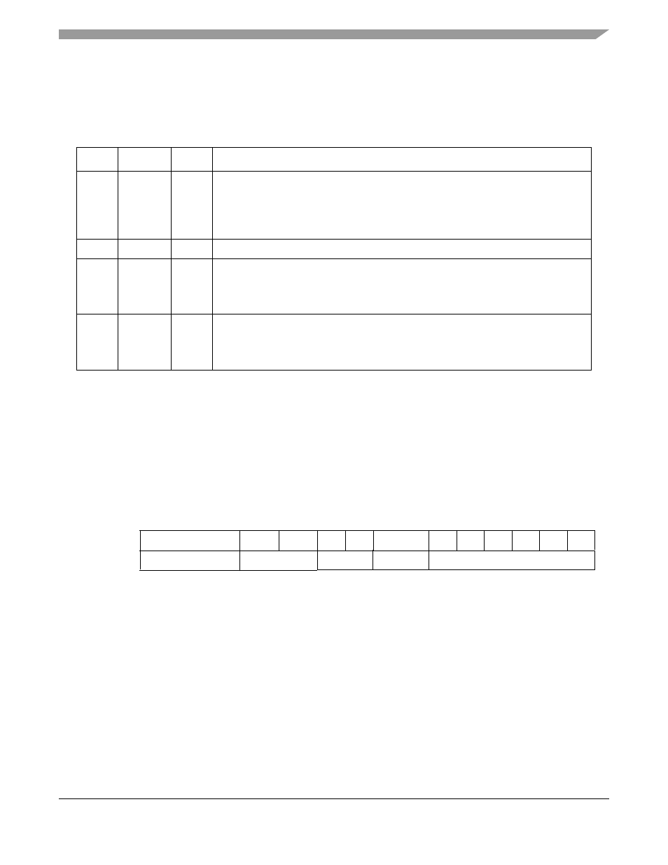
0
3
4
5
6
7
8
9
10
11
12
13
14
15
Interrupt Entry
—
SLIPE
SLIPS
UN
TXB
—
NID
IDL
MRF RXF BSY RXB
INTMSK
—
CES Mask Bits
Mask Bits
—
Mask Bits
Figure 28-7. INTMSK Mask Bits