10 smc uart txbd, Figure 27-8. smc uart txbd, Table 27-8. smc uart txbd field descriptions – Freescale Semiconductor MPC8260 User Manual
Page 829: Smc uart txbd -17, Smc uart txbd field descriptions -17
Serial Management Controllers (SMCs)
MPC8260 PowerQUICC II Family Reference Manual, Rev. 2
Freescale Semiconductor
27-17
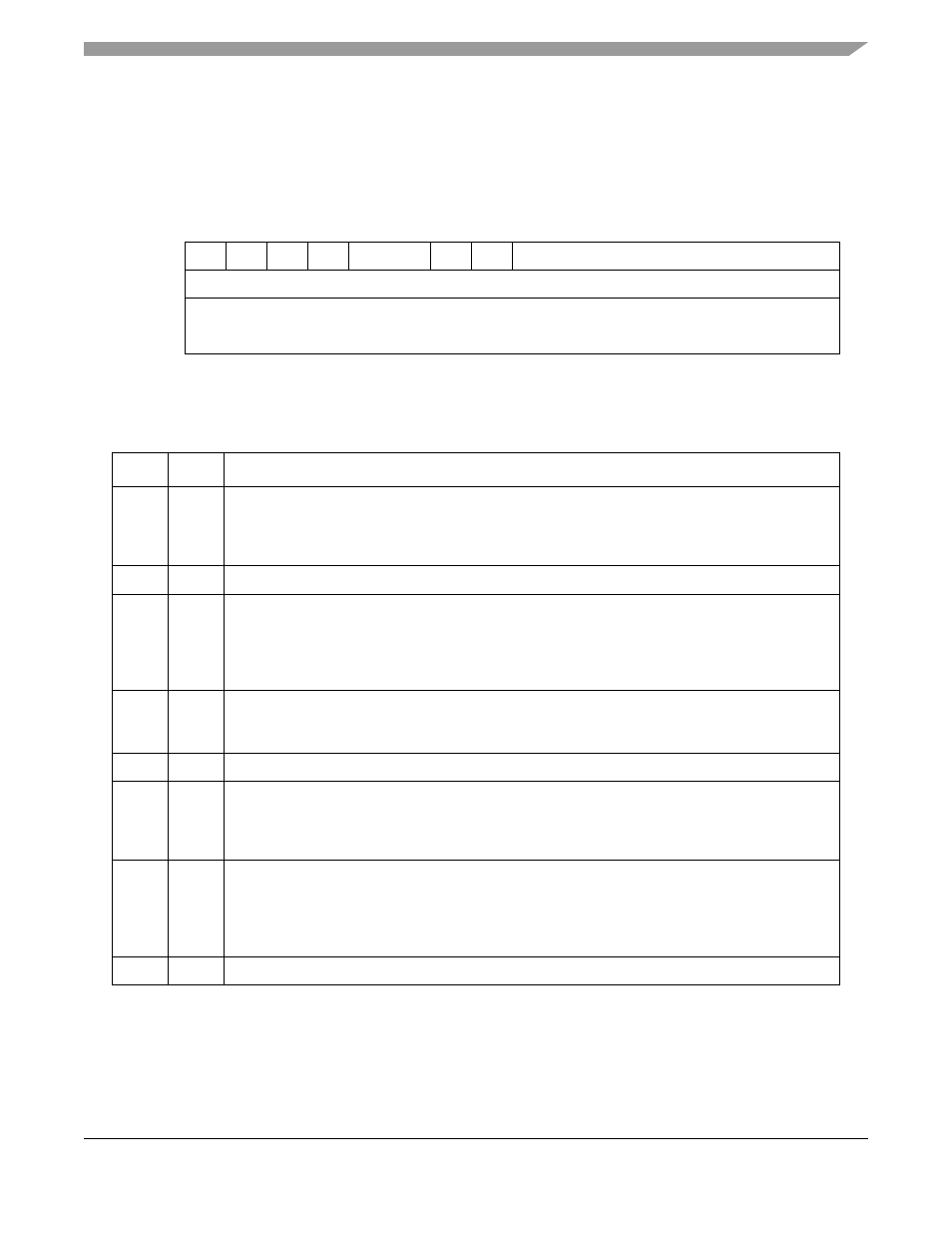
27.3.10 SMC UART TxBD
Data is sent to the CP for transmission on an SMC channel by arranging it in buffers referenced by the
channel TxBD table. Using the BDs, the CP confirms transmission or indicates error conditions so that the
processor knows the buffers have been serviced. An SMC UART TxBD is displayed in
.
describes SMC UART TxBD fields.
Data length represents the number of octets that the CP should transmit from this BD data buffer. However,
it is never modified by the CP and normally is greater than zero. It can be zero if P is set and only a
preamble is sent. If there are more than 8 bits in the UART character, data length should be even. For
example, to transmit three UART characters of 8-bit data, 1 start, and 1 stop, initialize the data length field
0
1
2
3
4
5
6
7
8
15
Offset + 0
R
—
W
I
—
CM
P
—
Offset + 2
Data Length
Offset + 4
Tx Data Buffer Pointer
Offset + 6
Figure 27-8. SMC UART TxBD
Table 27-8. SMC UART TxBD Field Descriptions
Bits
Name
Description
0
R
Ready
0 The buffer is not ready for transmission; BD and its buffer can be altered. The CP clears R after
the buffer has been sent or an error occurs.
1 The buffer has not been completely sent. This BD cannot updated while R is set.
1
—
Reserved, should be cleared.
2
W
Wrap (final BD in the TxBD table)
0 Not the last BD in the table.
1 Last BD in the table. After this buffer is used, the CP receives incoming data into the first BD that
TBASE points to. The number of TxBDs in this table is determined only by the W bit and overall
space constraints of the dual-port RAM.
3
I
Interrupt
0 No interrupt is generated after this buffer is serviced.
1 The SMCE[TXB] is set when this buffer is serviced. TXB can cause an interrupt if it is enabled.
4–5
—
Reserved, should be cleared.
6
CM
Continuous mode
0 Normal operation.
1 The CP does not clear R after this BD is closed and automatically retransmits the buffer when it
accesses this BD next.
7
P
Preamble
0 No preamble sequence is sent.
1 The UART sends one all-ones character before it sends the data so that the other end detects an
idle line before the data is received. If this bit is set and the data length of this BD is zero, only a
preamble is sent.
8–15
—
Reserved, should be cleared.