2 icp cell reception exceptions, Icp cell reception exceptions -51, Ima interrupt queue entry field descriptions -51 – Freescale Semiconductor MPC8260 User Manual
Page 1153: Table 33-23
Inverse Multiplexing for ATM (IMA)
MPC8260 PowerQUICC II Family Reference Manual, Rev. 2
Freescale Semiconductor
33-51
33.4.7.2
ICP Cell Reception Exceptions
ICP cells are received as AAL0 in the channel defined in RICPCH. Receive interrupts are provided for this
channel if enabled in its associated RCT.
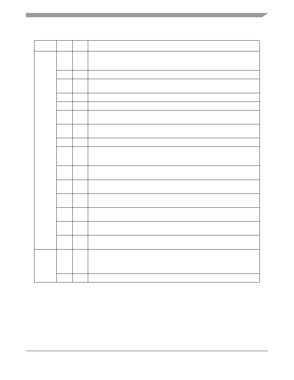
Table 33-23. IMA Interrupt Queue Entry Field Descriptions
Offset
Bits
Name
Description
Offset + 0 0
V
Valid interrupt entry.
0 This interrupt queue entry is free and can be used by the CP.
1 This interrupt queue entry is valid. The host should read this interrupt and clear this bit.
1
—
Reserved.
2
W
Wrap bit.When set, this is the last interrupt circular table entry. During initialization, the
host must clear all W bits in the table except the last one, which must be set.
3–4
—
Reserved
5
—
Reserved
6
TQU
Transmit queue underrun. Indicates that the corresponding PHY for this link requested a
cell for transmission, but the transmit queue was empty.
7
TQO
Transmit queue overflow. Indicates that the TRL attempted to send a cell to this link’s
transmit queue, but no space was available.
8
—
Reserved
9
DSL
DCB synchronization lost. This interrupt is issued when a link in a group with
IGRSTATE[GDSS] = 11 loses synchronization, and the link enters HUNT state at the
IFSM.
10
LS
Link stalled. A link in the round-robin cell extraction process has excessively stalled and
been deactivated (i.e. switched to filler mode by the microcode).
11
DCBO Link out of delay synchronization. Set when the link’s DCB overflows, indicating that delay
synchronization for this link is not possible.
12
LDS
Link delay synchronized. Set when delay synchronization is achieved for a link that has
been added to an existing group.
13
GDS
Group delay synchronized. Set when a group achieves delay synchronization as part of
the group startup procedure.
14
IFSD
IMA frame synchronization status = defect. Set when the associated link goes into the
Loss of IMA Frame Defect state of the Error/Maintenance State Machine.
15
IFSW
IMA frame synchronization status = working. Set when the associated link goes into the
IMA Working state of the Error/Maintenance State Machine.
Offset + 2 0
L/G
Link/group indicator. Indicates whether this interrupt is associated with a link or a group,
and thus if the NUM field is a link number or group number.
0 This interrupt is associated with a link.
1 This interrupt is associated with a group.
1–15
NUM
Link or group number associated with this interrupt.