Figure 4-24. ppc_alrl, Figure 4-25. lcl_acr, Table 4-11. lcl_acr field descriptions (continued) – Freescale Semiconductor MPC8260 User Manual
Page 203: Ppc_alrl -31, Lcl_acr -31, Lcl_acr field descriptions -31, Figure 4-24
System Interface Unit (SIU)
MPC8260 PowerQUICC II Family Reference Manual, Rev. 2
Freescale Semiconductor
4-31
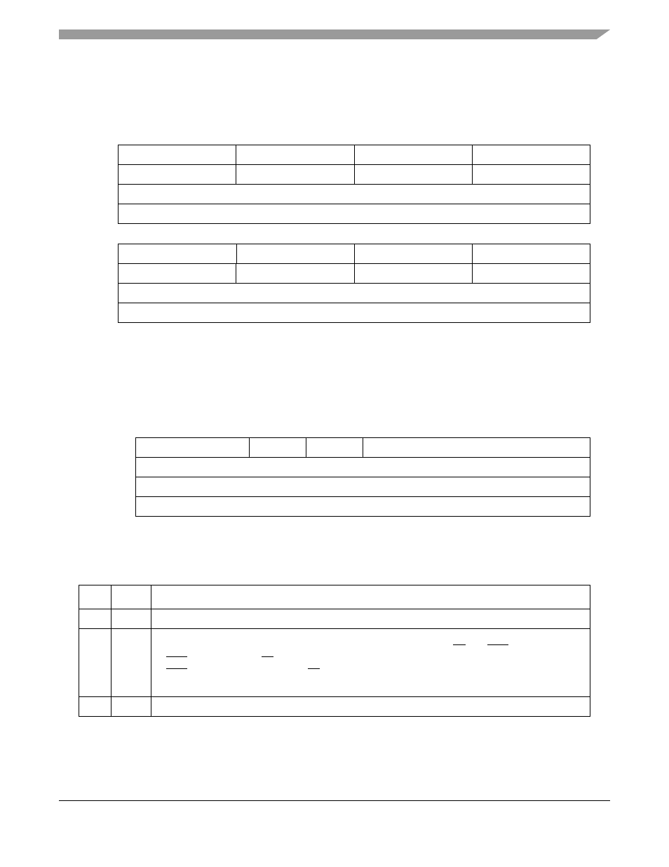
PPC_ALRL, shown in
, defines arbitration priority of 60x bus masters 8–15. Priority field 0 is
the highest-priority arbitration level. For information about the PowerQUICC II bus master indexes, see
the description of PPC_ACR[PRKM] in
.
4.3.2.4
Local Bus Arbiter Configuration Register (LCL_ACR)
The local bus arbiter configuration register (LCL_ACR), shown in
, defines the arbiter modes
and the parked master on the local bus.
describes LCL_ACR register bits.
0
3
4
7
8
11
12
15
Field
Priority Field 8
Priority Field 9
Priority Field 10
Priority Field 11
Reset
1000
1001
1010
1011
R/W
R/W
Addr
16
19
20
23
24
27
28
31
Field
Priority Field 12
Priority Field 13
Priority Field 14
Priority Field 15
Reset
1100
1101
1110
1111
R/W
R/W
Addr
0x10032
Figure 4-24. PPC_ALRL
0
1
2
3
4
7
Field
—
DBGD
—
PRKM
Reset
0000_0010
R/W
R/W
Addr
Figure 4-25. LCL_ACR
Table 4-11. LCL_ACR Field Descriptions
Bits
Name
Description
0–1
—
Reserved, should be cleared.
2
DBGD
Data bus grant delay. Specifies the minimum number of data tenure wait states for PowerPC
master-initiated data operations. This is the minimum delay between TS and DBG.
0 DBG is asserted with TS if the data bus is free.
1 DBG is asserted one cycle after TS if the data bus is not busy.
See
Section 8.5.1, “Data Bus Arbitration.”
3
—
Reserved, should be cleared.