Table 20-2. gsmr_l field descriptions (continued), Gsmr_l—general scc mode register (low order) -5, Gsmr_l field descriptions -5 – Freescale Semiconductor MPC8260 User Manual
Page 683
Serial Communications Controllers (SCCs)
MPC8260 PowerQUICC II Family Reference Manual, Rev. 2
Freescale Semiconductor
20-5
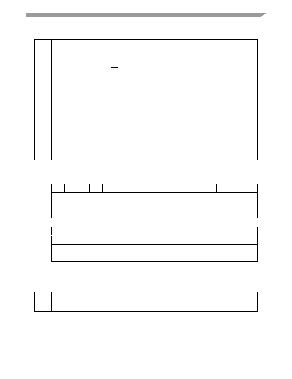
shows GSMR_L.
describes GSMR_L fields.
28–29
SYNL
Sync length (BISYNC and transparent mode only). See the data synchronization register (DSR)
definition in
Section 23.9, “Sending and Receiving the Synchronization Sequence
,” (BISYNC) and
Section 24.4.1.1, “In-Line Synchronization Pattern
,” (transparent).
00 An external sync (CD) is used instead of the sync pattern in the DSR.
01 4-bit sync. The receiver synchronizes on a 4-bit sync pattern stored in the DSR. This sync and
additional syncs can be stripped by programming the SCC’s parameter RAM for character
recognition.
10 8-bit sync. Should be chosen along with the BISYNC protocol to implement mono-sync. The
receiver synchronizes on an 8-bit sync pattern in the DSR.
11 16-bit sync. Also called BISYNC. The receiver synchronizes on a 16-bit sync pattern stored in
the DSR.
30
RTSM
RTS mode. Determines whether flags or idles are to be sent. Can be changed on-the-fly.
0 Send idles between frames as defined by the protocol and the TEND bit. RTS is negated between
frames (default).
1 Send flags/syncs between frames according to the protocol. RTS is always asserted whenever
the SCC is enabled.
31
RSYN
Receive synchronization timing (totally transparent mode only).
0 Normal operation.
1 If CDS = 1
,
CD should be asserted on the second bit of the Rx frame rather than on the first.
0
1
2
3
4
5
6
7
8
10
11
12
13
14
15
Field
—
EDGE
TCI
TSNC
RINV TINV
TPL
TPP
TEND
TDCR
Reset
0000_0000_0000_0000
R/W
R/W
Addr
0x0x11A00 (SCC1); 0x0x11A20 (SCC2); 0x0x11A40 (SCC3); 0x0x11A60 (SCC4)
16
17
18
20
21
23
24
25
26
27
28
31
Field
RDCR
RENC
TENC
DIAG
ENR ENT
MODE
Reset
0000_0000_0000_0000
R/W
R/W
Addr
0x11A02 (SCC1); 0x11A22 (SCC2); 0x11A42 (SCC3); 0x11A62 (SCC4)
Figure 20-3. GSMR_L—General SCC Mode Register (Low Order)
Table 20-2. GSMR_L Field Descriptions
Bit
Name
Description
0
—
Reserved, should be cleared.
Table 20-1. GSMR_H Field Descriptions (continued)
Bit
Name
Description