2 aal1 ces txbds, Figure 31-29. aal1 ces txbd, Aal1 ces txbds -40 – Freescale Semiconductor MPC8260 User Manual
Page 1056: Aal1 ces txbd -40, Aal1 ces txbd field descriptions -40
ATM AAL1 Circuit Emulation Service
MPC8260 PowerQUICC II Family Reference Manual, Rev. 2
31-40
Freescale Semiconductor
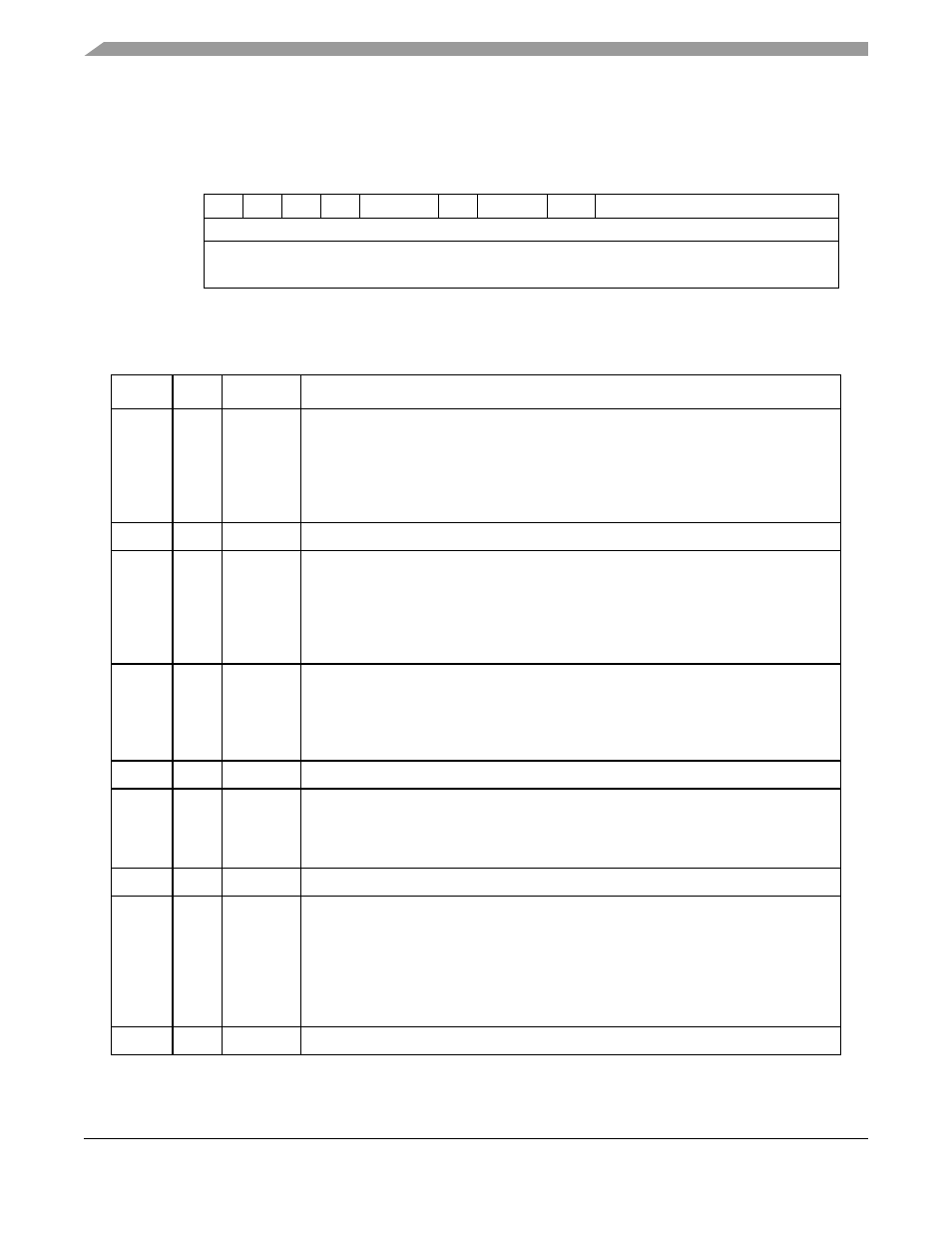
31.12.2 AAL1 CES TxBDs
shows the AAL1 CES TxBD.
describes AAL1 CES TxBD fields.
0
1
2
3
4
5
6
7
8
9
10
15
Offset + 0x00
R
—
W
I
—
CM
—
EOSF
—
Offset + 0x02
Data Length (DL)
Offset + 0x04
Tx Data Buffer Pointer (TXDBPTR)
Offset + 0x06
Figure 31-29. AAL1 CES TxBD
Table 31-12. AAL1 CES TxBD Field Descriptions
Offset
Bits
Name
Description
0x00
0
R
Ready
0 The buffer associated with this BD is not ready for transmission. The user is free to
manipulate this BD or its associated buffer. The CP clears this bit after the buffer has
been sent or after an error condition is encountered.
1 The buffer prepared for transmission by the user has not been sent or is being sent.
No fields of this BD may be written by the user once R is set.
1
—
—
2
W
Wrap (final BD in table)
0 Not the last BD in the TxBD table.
1 Last BD in the TxBD table. After this buffer is used, the CP sends outgoing data from
the first BD in the table (the BD pointed to by the channel’s TCT[TBD_BASE]). The
number of TxBDs in this table is determined only by the W bit. The current table
cannot exceed 64 Kbytes.
3
I
Interrupt
0 No interrupt is generated after this buffer has been serviced.
1 A Tx buffer event is sent to the interrupt queue after this buffer is serviced.
FCCE[GINT
x
] is set when the INT_CNT counter reaches the global interrupt
threshold.
4–5
—
—
6
CM
Continuous mode
0 Normal operation.
1 The CP does not clear the ready bit after this BD is closed, allowing the associated
buffer to be retransmitted automatically when the CP next accesses this BD.
7–8
—
—
9
EOSF
End of super frame. CES mode (TCT[CESM=1]) only.
0 No signaling information should be inserted after closing this buffer.
1 When closing this buffer the ATM transmitter fetches the CAS information from the
internal CAS block and packs it to the outgoing AAL1 cells.
Note that this bit should be set by the user at the end of each super-frame in the
common (MCC, ATM) BD table. See
Section 31.4.6, “Channel Associated Signaling
.”
10–15 —
—