Table 15-7. sixcmdr field description, 5 si status registers (sixstr), Figure 15-20. si status registers (sixstr) – Freescale Semiconductor MPC8260 User Manual
Page 601: Table 15-8. sixstr field descriptions, 6 serial interface idl interface support, Si status registers (sixstr) -25, Serial interface idl interface support -25, Sixcmdr field description -25, Sixstr field descriptions -25, Table 15-7
Serial Interface with Time-Slot Assigner
MPC8260 PowerQUICC II Family Reference Manual, Rev. 2
Freescale Semiconductor
15-25
15.5.5
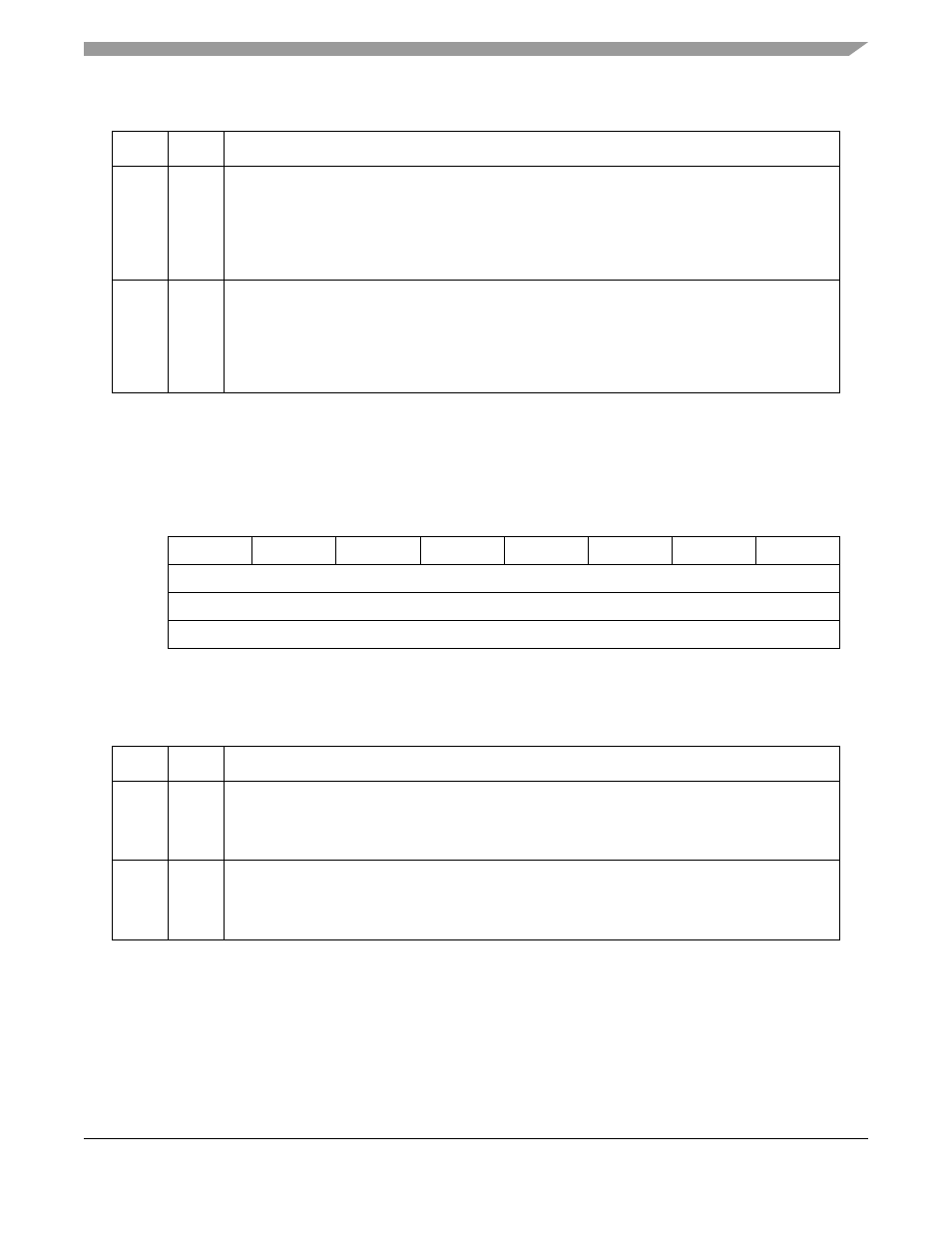
SI Status Registers (SI
x
STR)
The SI status register (SIxSTR), shown in
, identifies the current-route RAM. SIxSTR values
are valid only when the corresponding SIxCMDR bit = 0.
describes SIxSTR fields.
15.6
Serial Interface IDL Interface Support
The IDL interface is a full-duplex ISDN interface used to connect a physical layer device to the
PowerQUICC II. The PowerQUICC II supports both the basic and primary rate of the IDL bus. In the basic
rate of IDL, data on three channels (B1, B2, and D) is transferred in a 20-bit frame, providing a full-duplex
bandwidth of 160 Kbps. The PowerQUICC II is an IDL slave device that is clocked by the IDL bus master
Table 15-7. SI
xCMDR Field Description
Bits
Name
Description
0, 2, 4,
6
CSRRx Change shadow RAM for TDM a, b, c, or d receiver. Set CSRRx causes the SI receiver to replace
the current route RAM with the shadow RAM. Set by the user and cleared by the SI.
0 The receiver shadow RAM is not valid. The user can write into the shadow RAM to program a
new routing.
1 The receiver shadow RAM is valid. The SI exchanges between the RAMs and take the new
receive routing from the receiver shadow RAM. Cleared as soon as the switch has completed.
1, 3, 5,
7
CSRTx Change shadow RAM for TDM a, b, c, or d transmitter. Set CSRTx causes the SI transmitter to
replace the current route RAM with the shadow RAM. Set by the user and cleared by the SI.
0 The transmitter shadow RAM is not valid. The user can write into the shadow RAM to program a
new routing.
1 The transmitter shadow RAM is valid. The SI exchanges between the RAMs and take the new
transmitter routing from the receiver shadow RAM. Cleared as soon as the switch has completed.
0
1
2
3
4
5
6
7
Field
CRORA
CROTA
CRORB
CROTB
CRORC
CROTC
CRORD
CROTD
Reset
0000_0000
R/W
R
Addr
0x0x11B2C (SI1STR), 0x0x11B4C (SI2STR)
Figure 15-20. SI Status Registers (SI
xSTR)
Table 15-8. SI
xSTR Field Descriptions
Bits
Name
Description
0, 2, 4,
6
CROR
x
Current-route original receiver. Determines whether the current-route receiver RAM is the original
or the shadow.
0 The current-route receiver RAM is the lower address area.
1 The current-route receiver RAM is the upper address area.
1, 3, 5,
7
CROTx Current-route original transmitter. Determines whether the current-route transmitter RAM is the
original or the shadow.
0 The current-route transmitter RAM is the lower address area.
1 The current-route transmitter RAM is the upper address area.