Table 31-4. aal1 ces parameters, Aal1 ces parameters -25, Table 31-4 – Freescale Semiconductor MPC8260 User Manual
Page 1041
ATM AAL1 Circuit Emulation Service
MPC8260 PowerQUICC II Family Reference Manual, Rev. 2
Freescale Semiconductor
31-25
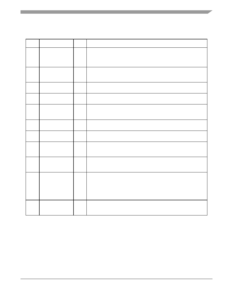
Additional CES parameters needed by the AAL1 microcode are described in the following table.
31.9
Receive and Transmit Connection Tables
(RCT, TCT)
The connection tables, RCT and TCT, hold channel configuration and temporary parameters for each
receive and transmit channel (AAL type, connection traffic parameters, BDs’ parameters and temporary
parameters used during segmentation and reassembly).
The internal connection tables hold parameters for up to 128 channels (channels 0–127). In extended
channel mode, parameters for channels 256 and above are kept in external memory. The only relationship
Table 31-4. AAL1 CES Parameters
Offset
Name
Width
Description
0x4A
INT_RTCRT_BASE
Hword
Internal receive/transmit CAS routing table extension base. User-defined. Note
that because AAL1 CES does not need the TCT extension, the AAL1 CES
microcode uses this Hword to point to a CAS routing table. Should be 32 byte
aligned. User-defined.
0x58
EXT_RTCRT_BASE Word
External receive/transmit CAS routing table extension base. User-defined. Note
that because AAL1 CES does not need the TCT extension, the AAL1 CES
microcode uses this word to point to a CAS routing table.
0xB2
AAL1_INT_RX_CRT Hword
(CES only) Points to a reserved scratchpad area of 32 bytes in the dual-port
RAM used by the CES microcode. Should be 32 byte aligned. User-defined.
0xd0
OCASSR
Byte
Outgoing CAS Status Register. See
Section 31.10, “Outgoing CAS Status
0xE0
TCELL_TMP_BASE
_EXT
Word
Transmit Cell Temporary base address (64-byte aligned). Points to an external
memory block reserved for partially filled cells (64 octets for each CES
channel). This area is allocated by the user but used by the CP.
0xE4
IN_CAS_BLOCK_B
ASE
Hword
Incoming CAS Block Base (depicted in
). Points to dual-port RAM.
Should be 32-byte aligned. User-defined.
0xE6
OUT_CAS_BLOCK_
BASE
Hword
Outgoing CAS Block Base (depicted in
). Points to dual-port RAM.
Should be 32-byte aligned. User-defined.
0xE8
AAL1_Int_STATT_B
ASE
Hword
AAL1 Internal Statistics Table Base. Points to dual-port RAM. Should be 16-byte
aligned. User-defined. See
Section 31.15, “Internal AAL1 CES Statistics
.
”
0xEA
AAL1_DUMMY_CEL
L_BASE
Hword
ALL1 Dummy cell base address. Points to dual-port RAM area contains the
AAL1 dummy cell template (little-endian format). Should be 64-byte aligned.
User-defined.
0xEC
CATB
Hword
CES adaptive threshold tables base address. Points to the dual-port RAM area
containing the CES slip control thresholds and the adaptive counter See
Section 31.15, “Internal AAL1 CES Statistics Tables
”
Should be 8-byte aligned
(8 octets for each AAL1-MCC channel). User-defined and should match the
CATB value programmed in the MCC parameter RAM; see
“MCC Parameters for AAL1 CES Usage
.”
0xF0
AAL1_Ext_STATT_B
ASE
Word
AAL1 External Statistics Table Base. Points to External memory. Should be
16-byte aligned (16 octets for each AAL1 channel).User-defined. See