Table 10-3. scmr field descriptions, Figure 10-7. relationships of scmr parameters, Relationships of scmr parameters -10 – Freescale Semiconductor MPC8260 User Manual
Page 416: Scmr field descriptions -10, Table 10-3, Ee table 10-3, Scmr[corecnf] bit values are s hown in table 10-4
Clocks and Power Control
MPC8260 PowerQUICC II Family Reference Manual, Rev. 2
10-10
Freescale Semiconductor
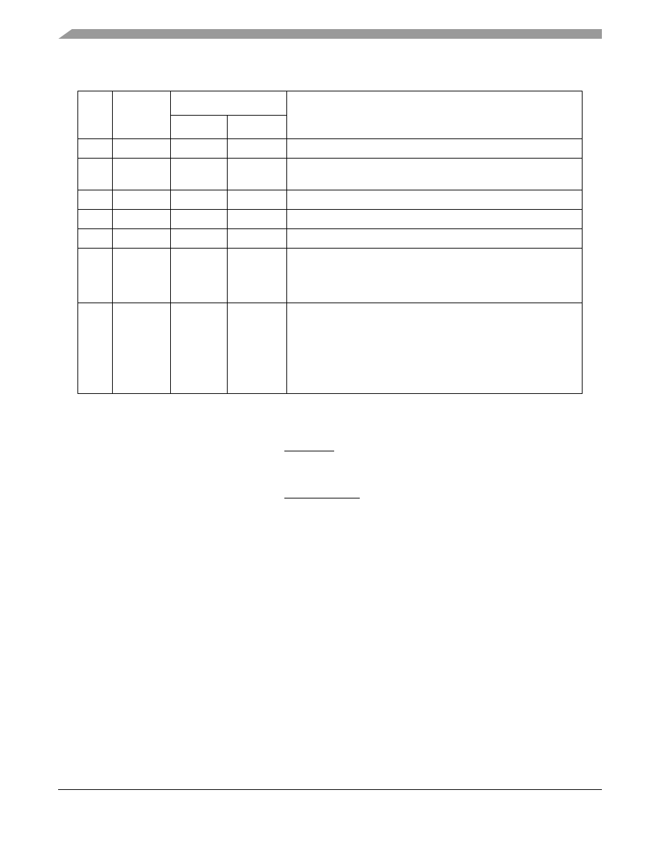
The relationships among these parameters are described in the formulas in
.
Figure 10-7. Relationships of SCMR Parameters
SCMR[CORECNF] bit values are shown in
Table 10-3. SCMR Field Descriptions
Bits
Name
Defaults
Description
POR
Hard Reset
0–2
—
—
—
Reserved
3–7
CORECNF
Config pins
Unaffected
Core configuration. PLL configuration of the core. These values are
reflect the values of PLL_CFG[0:5], described in Table 10-4.
8–11
BUSDF
Config pins
Unaffected
60x bus division factor
12–15
CPMDF
Config pins
Unaffected
CPM division factor. This value is always 1.
16–18
—
—
—
Reserved
19
PLLDF
Config pins
Unaffected
PLL pre-divider factor. Ensures that PLLMF is an integer value
regardless of whether the ratio CPM_CLK/CLKIN is an integer.
0 CPM_CLK/CLKIN is an integer. (The PLL division factor is 1.)
1 CPM_CLK/CLKIN is not an integer. (The PLL division factor is 2.)
20–31
PLLMF
Config pins
Unaffected
PLL multiplication factor. (A PLLMF value of 0x000 corresponds to 1,
and 0xFFF to 4,096.) The VCO output is divided to generate the
feedback signal that goes to the phase comparator. PLLMF and
PLLDF bits control the value of the divider in the PLL feedback loop.
The phase comparator determines the phase shift between the
feedback signal and the reference clock. This difference causes an
increase or decrease in the VCO output frequency.
PLLMF = CPM_CLK
CLKIN
×
(PLLDF + 1) – 1
BUSDF = (PLLMF + 1)
×
2
(PLLDF + 1)
– 1