1 internal transmitter state (tstate)-hdlc mode, Figure 28-2. tstate high byte, Table 28-3. tstate high-byte field descriptions – Freescale Semiconductor MPC8260 User Manual
Page 855: Internal transmitter state (tstate)—hdlc mode -7, Tstate high byte -7, Tstate high-byte field descriptions -7, Section 28.3.1.1, “internal, Transmitter state (tstate)—hdlc mode, 1 internal transmitter state (tstate)—hdlc mode
Multi-Channel Controllers (MCCs)
MPC8260 PowerQUICC II Family Reference Manual, Rev. 2
Freescale Semiconductor
28-7
28.3.1.1
Internal Transmitter State (TSTATE)—HDLC Mode
Internal transmitter state (TSTATE) is a 4-byte register provides transaction parameters associated with
SDMA channel accesses (like function code registers) and starts the transmitter channel.
To start the channel, write 0xHH800000 to TSTATE, where HH is the TSTATE high byte (see
). When the channel is active, the CP changes the value of the three LSBs, hence these 3 bytes
must be masked if the user reads back the TSTATE.
TSTATE high-byte fields are described in
0x38
MFLR
Hword Maximum frame length register. Defines the longest expectable frame for this channel.
(64-Kbyte maximum). The remainder of a frame that is larger than MFLR is discarded
and the LG flag is set in the last frame’s BD. An interrupt request might be generated
(RXF and RXB) depending on the interrupt mask. A frame’s length is considered to be
everything between flags, including CRC. No more data is written into the current buffer
when the MFLR violation is detected.
0x3A
MAX_CNT Hword Max_length counter, used by the CP (read-only for the user)
0x3C
RCRC
Word
Temp receive CRC, used by the CP (read-only for the user)
1
The offset is relative to dual-port RAM (DPRAM) base address + 64*CH_NUM
0
1
2
3
4
5
6
7
Field
—
GBL
BO
TC2
DTB
BDB
Reset
—
R/W
R/W
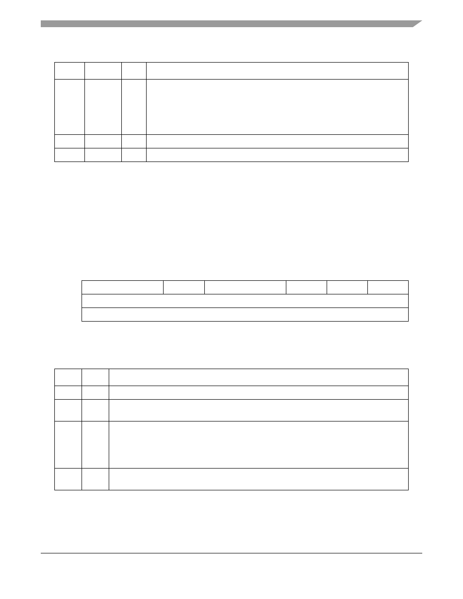
Figure 28-2. TSTATE High Byte
Table 28-3. TSTATE High-Byte Field Descriptions
Bits
Name
Description
0–1
—
Reserved, should be cleared.
2
GBL
Global. Setting GLB activates snooping (only the 60X bus can be snooped, this parameter is ignored
for local bus transactions).
3–4
BO
Byte ordering. Set BO to select the required byte ordering for the buffer. If BO is changed on-the-fly,
it takes effect at the beginning of the next frame or at the beginning of the next BD.
00 Reserved
01 Munged little-endian.
1x Big-endian
5
TC2
Transfer code. Contains the transfer code value of TC[2], used during this SDMA channel memory
access. TC[0–1] is driven with a 0b11 to identify this SDMA channel access as a DMA-type access.
Table 28-2. Channel-Specific Parameters for HDLC (continued)
Offset
1
Name
Width
Description