Freescale Semiconductor MPC8260 User Manual
Page 675
SDMA Channels and IDMA Emulation
MPC8260 PowerQUICC II Family Reference Manual, Rev. 2
Freescale Semiconductor
19-31
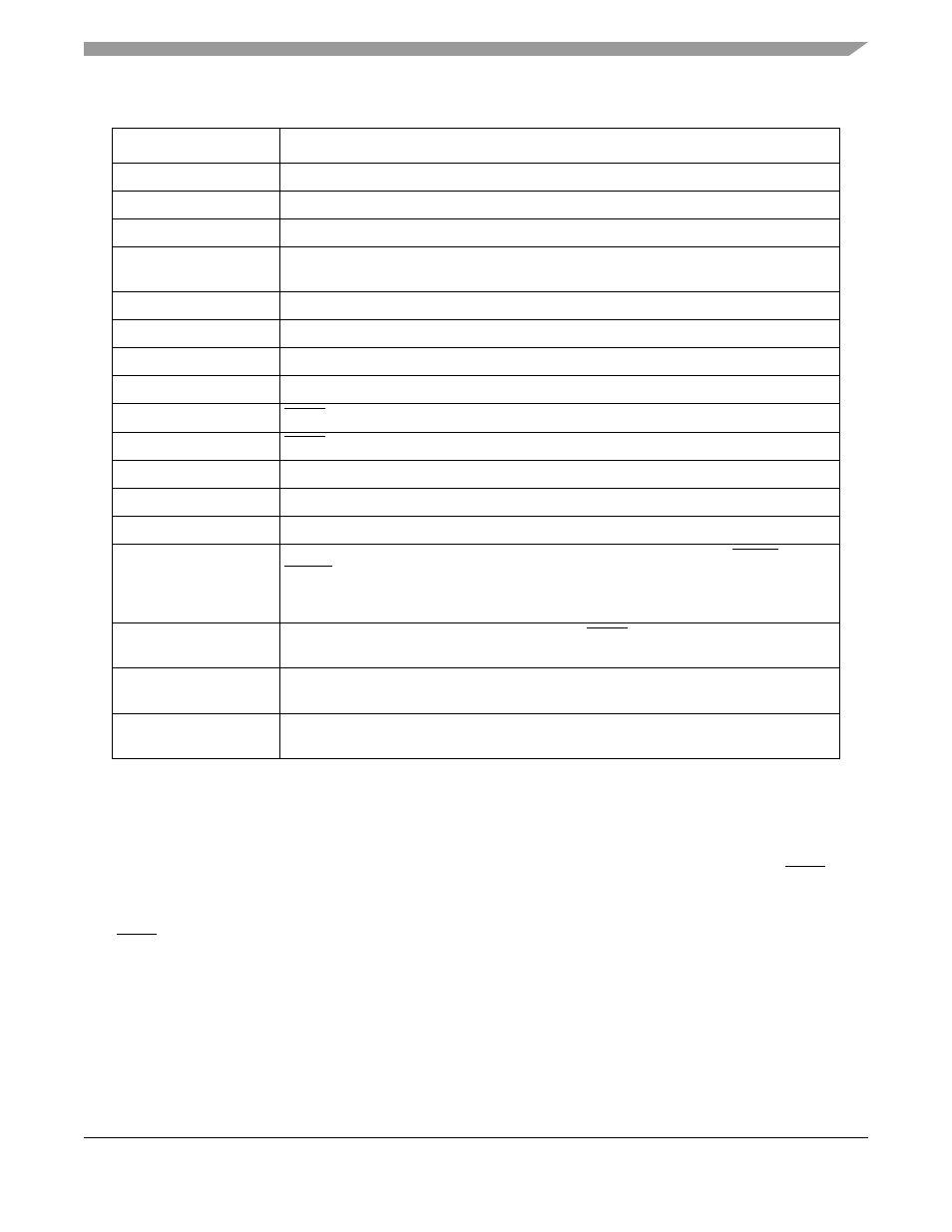
DCM(SINC) = 0
The peripheral address are not incremented after transfers, fixed location.
DCM(DINC) = 1
The memory address is incremented after every transfer.
DPR_BUF = 0x0DC0
Initiated to address aligned to 64 (bit[5–0]= 00000).
IBASE = IBDPTR =
0x0030
The current BD pointer is set to the BD table base address (aligned 16 -bits[3–0] = 0).
STS = 8 (0x0008)
Transfers from peripheral are always single 8-byte accesses.
DTS = 32 (0x0020)
Transfers to memory are 32 bytes long (60x bursts) on steady-state of work.
Every BD(SDTB) = 0
Peripheral is on the 60x bus.
Every BD(DDTB) = 1
Memory is on the local bus.
Last BD(SDN) = 1
DONE is asserted on the last transfer from peripheral.
Last BD(DDN) = 0
DONE is not asserted on the last transfer to memory.
Every BD(DL) = k*STS
Data length must be STS modular (divided by STS without residue).
IDMR2 = 0x0300_0000
IDMA2 Mask register is programmed to enable EDN and BC interrupts only.
SIMR_L = 0x0000_0200
Interrupt controller is programmed to enable interrupts from IDMA2.
PDIRC = 0x1000_0000
PPARC = 0x7000_0000
PSORC = 0x3000_0000
PODRC = 0x2000_0000
Parallel I/O registers are programmed to enable:PC[1] = DREQ2; PC[3] = DACK2; PC[2] =
DONE2.
The peripheral signals are to be connected to these lines accordingly.
RCCR = 0x0000_0000
IDMA2 configuration: DREQ is edge low-to-high. DONE is high-to-low. Request priority is
higher than the SCCs.
88FE = 0x0300
IDMA2_BASE points to 0x0300 where the parameter table base address is located for
IDMA2.
CPCR = 0x22A1_0009
START
_
IDMA
command. IDMA2 page-01000 SBC-10101 op-1001 FLG=1.This write starts
the channel operation.
DMA operation description:
START
_
IDMA
: Initialize all parameter RAM values, wait for DREQ to open the first BD. The four first DREQs trigger
single, 8-byte read transactions from the peripheral until data in the internal buffer is 32 bytes long. Then, a write
transaction to memory is done with the size needed for alignment.
Steady state: Every DREQ assertion triggers a read transaction of 8 bytes from the peripheral. If the data in the internal
buffer is more than 31 bytes a write transaction to memory of 32 bytes (one local burst) follows immediately. Memory
address is incremented constantly. Last read transaction of the last BD from the peripheral is combined with DONE
assertion.
STOP
_
IDMA
: After all data in internal buffer is written to memory in one transfer, SC bit is set in IDSR (SC interrupt to
the core is not enabled) and BD is closed. Channel is stopped until
START
_
IDMA
command is reissued.
DONE assertion by the peripheral: All data in internal buffer is written to memory in one transfer. At the end of the
transfer, EDN interrupt is set to host. Additional DREQ assertions are ignored. IDMA2 channel is stopped until
START
_
IDMA
command is issued.
Table 19-15. Example: Peripheral-to-Memory Mode—IDMA2 (continued)
Important Init Values
Description