7 bisync sync register (bsync), Figure 23-3. bisync sync (bsync), Bisync sync register (bsync) -7 – Freescale Semiconductor MPC8260 User Manual
Page 757: Bisync sync (bsync) -7, Section 23.7, “bisync sync register (bsync)
SCC BISYNC Mode
MPC8260 PowerQUICC II Family Reference Manual, Rev. 2
Freescale Semiconductor
23-7
23.7
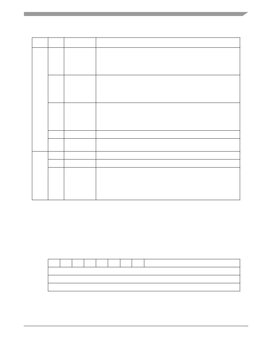
BISYNC SYNC Register (BSYNC)
The BSYNC register, shown in
, defines BISYNC stripping and SYNC character insertion.
When an underrun occurs, the BISYNC controller inserts SYNC characters until the next buffer is
available for transmission. If the receiver is not in hunt mode when a SYNC character is received, it
discards this character if the valid bit (BSYNC[V]) is set.When using 7-bit characters with parity, the
parity bit should be included in the SYNC register value.
describes BSYNC fields.
Table 23-4. Control Character Table and RCCM Field Descriptions
Offset
Bit
Name
Description
0x42–
0x50
0
E
End of table.
0 This entry is valid. The lower eight bits are checked against the incoming
character. In tables with eight control characters, E should be zero in all eight
positions.
1 The entry is not valid. No other valid entries exist beyond this entry.
1
B
BCS expected. A maskable interrupt is generated after the buffer is closed.
0 The character is written into the receive buffer and the buffer is closed.
1 The character is written into the receive buffer. The receiver waits for one LRC
or two CRC bytes of BCS and then closes the buffer. This should be used for
ETB, ETX, and ITB.
2
H
Hunt mode. Enables hunt mode when the current buffer is closed.
0 The BISYNC controller maintains character synchronization after closing this
buffer.
1 The BISYNC controller enters hunt mode after closing the buffer. When the B
bit is set, the controller enters hunt mode after receiving the BCS.
3–7
—
Reserved
8–15
CHARACTER
n
Control character 1–8. When using 7-bit characters with parity, include the parity
bit in the character value.
0x52
0–2
—
All ones.
3–7
—
Reserved
8–15
RCCM
Received control character mask. Masks comparison of CHARACTER
n
. Each bit
of RCCM masks the corresponding bit of CHARACTER
n
.
0 Mask this bit in the comparison of the incoming character and CHARACTER
n
.
1 The address comparison on this bit proceeds normally and no masking occurs.
If RCCM is not set, erratic operation can occur during control character
recognition.
0
1
2
3
4
5
6
7
8
15
Field
V
DIS
0
0
0
0
0
0
SYNC
Reset
Undefined
R/W
R/W
Addr
SCC Base + 0x3E
Figure 23-3. BISYNC SYNC (BSYNC)