2 hard reset configuration examples, 1 single powerquicc ii with default configuration, Figure 5-5. single chip with default configuration – Freescale Semiconductor MPC8260 User Manual
Page 232: 2 single powerquicc ii configured from boot eprom, Hard reset configuration examples -10, Single chip with default configuration -10, Section 5.4.2, “hard reset configuration, Examples
Reset
MPC8260 PowerQUICC II Family Reference Manual, Rev. 2
5-10
Freescale Semiconductor
5.4.2
Hard Reset Configuration Examples
This section presents some examples of hard reset configurations in different systems.
5.4.2.1
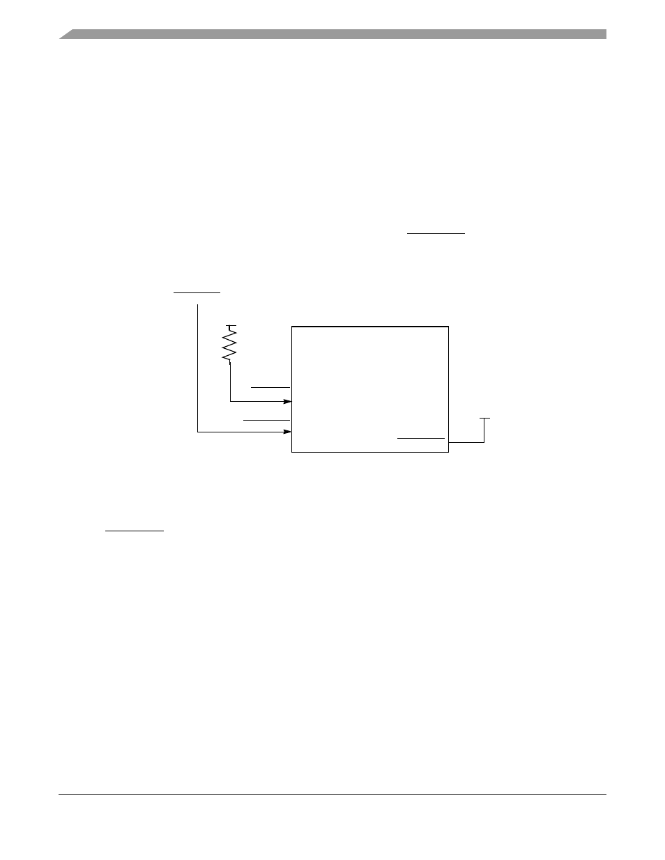
Single PowerQUICC II with Default Configuration
This is the simplest configuration scenario. It can be used if the default values achieved by clearing the
hard reset configuration word are desired. This is applicable only for systems using single-PowerQUICC
II bus mode (as opposed to 60x bus mode). To enter this mode, tie RSTCONF to V
CC
as shown in
. The PowerQUICC II does not access the boot EPROM; it is assumed that the default
configuration is used upon exiting hard reset.
Figure 5-5. Single Chip with Default Configuration
5.4.2.2
Single PowerQUICC II Configured from Boot EPROM
For a configuration that differs from the default, the PowerQUICC II can be used as a configuration master
by tying RSTCONF to GND as shown in
. The PowerQUICC II can access the boot EPROM.
It is assumed the configuration is as defined there upon exiting hard reset.
1
The user should exercise caution when changing this bit. This bit has an immediate effect on the external bus and
may result in unstable system operation.
Configuration
Slave Chip
PORESET
PORESET
RSTCONF
D[0–31]
A[0–31]
HRESET
Vcc
Vcc