Figure 29-8. output delay from rts asserted, Figure 29-9. output delay from cts asserted, Output delay from rts asserted -18 – Freescale Semiconductor MPC8260 User Manual
Page 916: Output delay from cts asserted -18
Fast Communications Controllers (FCCs)
MPC8260 PowerQUICC II Family Reference Manual, Rev. 2
29-18
Freescale Semiconductor
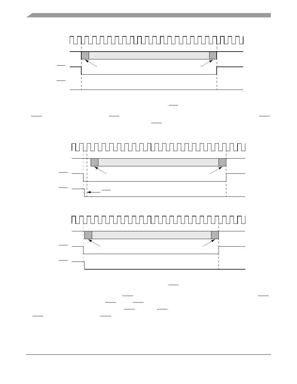
Figure 29-8. Output Delay from RTS Asserted
If CTS is not already asserted when RTS is asserted, the delays to the first bit of data depend on when CTS
is asserted.
shows that the delay between CTS and the data can be approximately 0.5 to 1 bit
times or no delay, depending on GFMR[CTSS].
Figure 29-9. Output Delay from CTS Asserted
If it is programmed to envelope the data, CTS must remain asserted during frame transmission or a CTS
lost error occurs. The negation of CTS forces RTS high and the transmit data to the idle state. If
GFMR[CTSS] = 0, the FCC must sample CTS before a CTS lost is recognized. Otherwise, the negation
of CTS immediately causes the CTS lost condition. See
1. A frame includes opening and closing flags and syncs, if present in the protocol.
TCLK
TXD
Last Bit of Frame Data
First Bit of Frame Data
Note:
(Output)
RTS
(Output)
CTS
(Input)
1. GFMR[CTSS] = 0. CTSP is a don’t care.
TCLK
TXD
Last Bit of Frame Data
First Bit Of Frame Data
Note:
CTS Sampled Low
1. GFMR[CTSS] = 1. CTSP is a don’t care.
TCLK
TXD
Last Bit of Frame Data
First Bit of Frame Data
Note:
(Output)
RTS
(Output)
CTS
(Input)
(Output)
RTS
(Output)
CTS
(Input)