Table 19-4. idmax parameter ram (continued), Idmax parameter ram -18, Table 19-4 – Freescale Semiconductor MPC8260 User Manual
Page 662
SDMA Channels and IDMA Emulation
MPC8260 PowerQUICC II Family Reference Manual, Rev. 2
19-18
Freescale Semiconductor
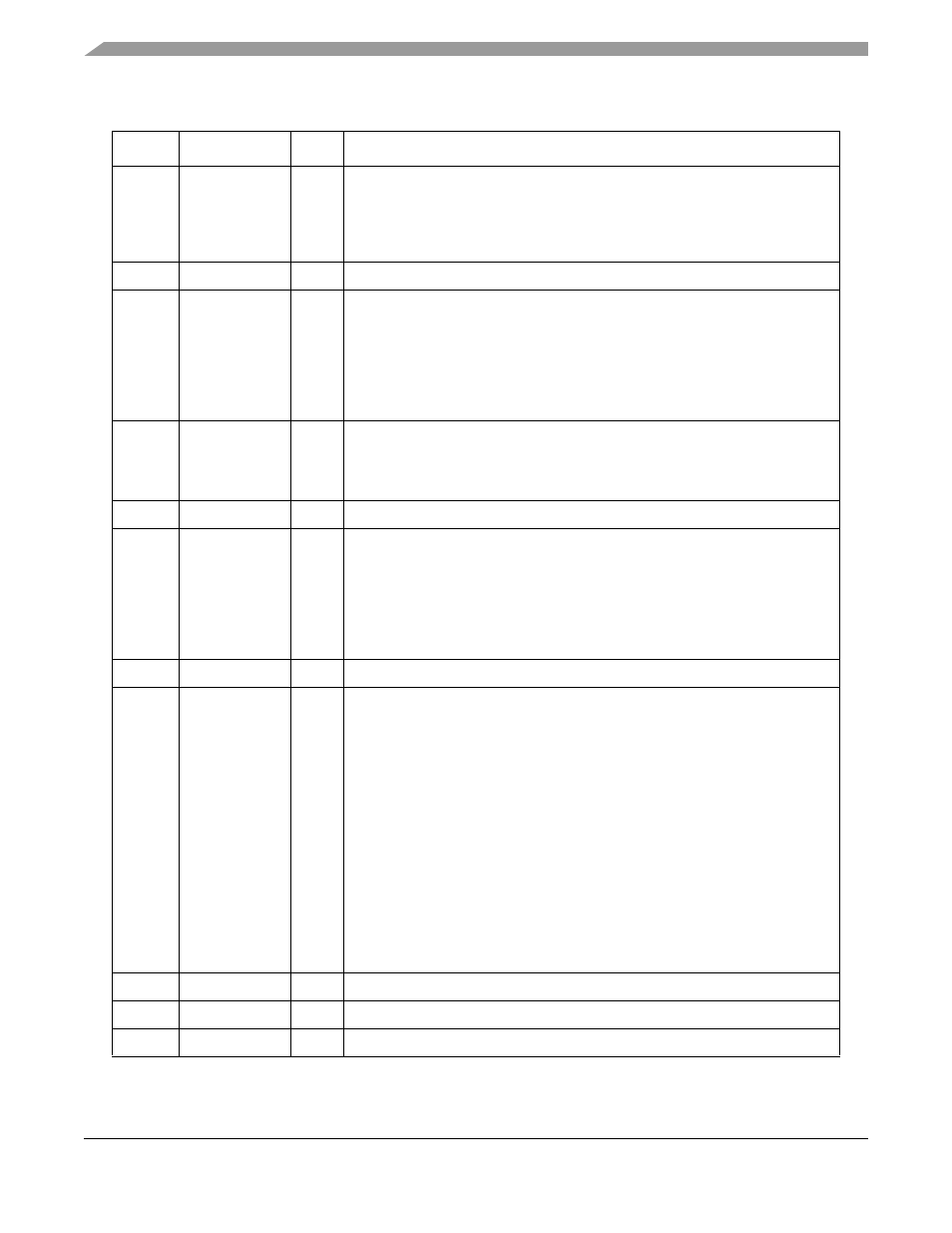
Table 19-4. IDMA
x Parameter RAM
Offset
1
Name
Width
Description
0x00
IBASE
Hword IDMA BD table base address. Defines the starting location in the dual-port RAM
for the set of IDMA BDs. It is an offset from the beginning of the dual-port RAM.
The user must initialize IBASE before enabling the IDMA channel and should not
overlap BD tables of two enabled serial controllers or IDMA channels or erratic
operation results. IBASE should be 16-byte aligned.
0x02
DCM
Hword DMA channel mode. See
Section 19.8.2.1, “DMA Channel Mode (DCM)
.”
0x04
IBDPTR
Hword IDMA BD pointer. Points to the current BD during transfer processing. Points to
the next BD to be processed when an idle channel is restarted. Initialize to
IBASE before the first
START
_
IDMA
command. If BD[W] = 1, the CP initializes
IBPTR to IBASE When the end of an IDMA BD table is reached. After a
STOP
_
IDMA
command is issued, IBDPTR points to the next BD to be processed.
It can be modified after SC interrupt is set and before a
START
_
IDMA
command
is reissued.
0x06
DPR_BUF
Hword IDMA transfer buffer base address. The base address should be aligned
according to the buffer size determined by DCM[DMA_WRAP]. The transfer
buffer size should be consistent with DCM[DMA_WRAP]; that is, DPR_BUF =
(64 X 2
DMA_WRAP
). See
Section 19.8.2.1, “DMA Channel Mode (DCM)
.”
0x08
BUF_INV
Hword Internal buffer inventory. Indicates the quantity of data inside the internal buffer.
0x0A
SS_MAX
Hword Steady-state maximum transfer size in bytes. User-defined parameter to
increase microcode efficiency. Initialize to internal_buffer_size - 32, that is,
SS_MAX = (64 X 2
DMA_WRAP
) - 32. If possible, SS_MAX is used as the transfer
size on transfers to/from memory in memory-to-peripheral mode or in
peripheral-to-memory mode. For memory-to-memory mode, SS_MAX is used
as the transfer size for at least one of the devices. SS_MAX should be consistent
with STS, DTS, and DCM[S/D]. See
and
.
0x0C
DPR_IN_PTR
Hword Write pointer inside the internal buffer.
0x0E
STS
Hword Source transfer size in bytes. All transfers from the source (except the start
alignment and the end) are written to the bus using this parameter.
In memory-to-peripheral mode, STS should be initialized to SS_MAX.
In peripheral-to-memory mode, STS should be initialized to the peripheral port
size or peripheral transfer size (if the peripheral accepts bursts). See
for valid STS values for peripherals.
In fly-by mode, STS is initialized to the peripheral port size.
In memory-to-memory mode:
• STS should be initialized to SS_MAX.
• DTS value should be initialized to SS_MAX. STS can be initialized to values
other than SS_MAX in the following conditions:
– STS must divide SS_MAX.
– STS must be divided by 32 to enable bursts during the steady-state phase.
• See
for memory-to-memory valid STS values.
0x10
DPR_OUT_PTR Hword Read pointer inside the internal buffer.
0x12
SEOB
Hword Source end of burst. Used for alignment of the first read burst.
0x14
DEOB
Hword Destination end of burst. Used for alignment of the first write burst.