7 internal memory map register (immr), Figure 4-29. internal memory map register (immr), Internal memory map register (immr) -36 – Freescale Semiconductor MPC8260 User Manual
Page 208: Section 4.3.2.7, “internal memory, Map register (immr)
System Interface Unit (SIU)
MPC8260 PowerQUICC II Family Reference Manual, Rev. 2
4-36
Freescale Semiconductor
4.3.2.7
Internal Memory Map Register (IMMR)
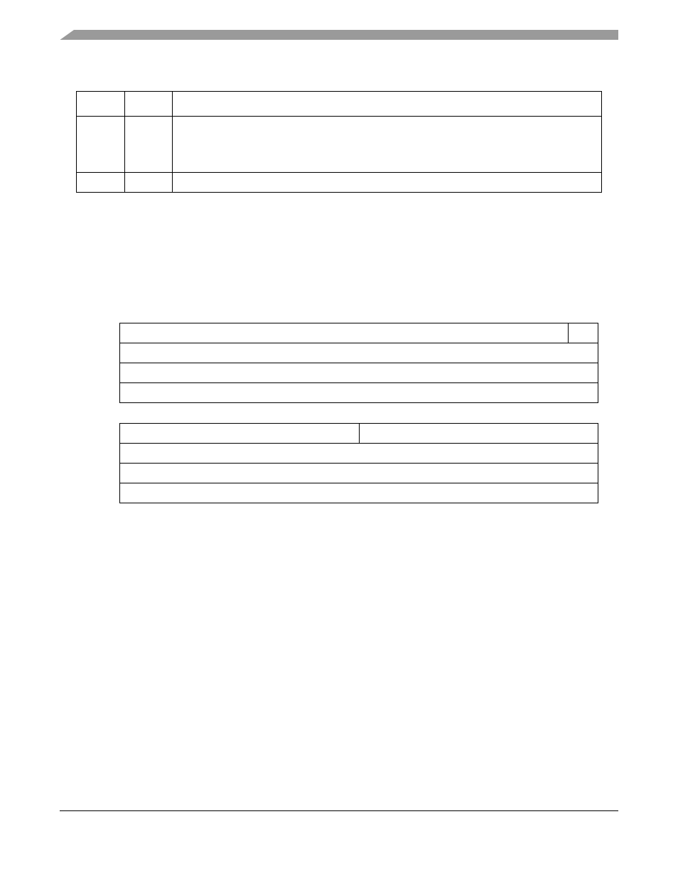
The internal memory map register (IMMR), shown in
, contains identification of a specific
device as well as the base address for the internal memory map. Software can deduce availability and
location of any on-chip system resources from the values in IMMR. PARTNUM and MASKNUM are
mask programmed and cannot be changed for any particular device.
describes IMMR fields.
18
LPBSE
Local bus parity byte select enable.
0 Parity byte select is disabled. LGPL4 output of UPM is available for memory control.
1 Parity byte select is enabled. LGPL4 pin is used as local bus parity byte select output from the
PowerQUICC II.
19–31
—
Reserved, should be cleared.
0
14
15
Field
ISB
—
Reset
Depends on reset configuration sequence. See
Section 5.4.1, “Hard Reset Configuration Word.”
R/W
R/W
Addr
16
23
24
31
Field
PARTNUM
MASKNUM
Reset
0x0011 (.29
µm Rev A.1); 0x0023 (.29µm Rev B.3); 0x0024 (.29µm Rev C.2); 0x0060 (.25µm Rev A.0)
R/W
R
Addr
0x101AA
Figure 4-29. Internal Memory Map Register (IMMR)
Table 4-12. SIUMCR Register Field Descriptions (continued)
Bits
Name
Description