6 idcr counter algorithm, 7 idcr events, Idcr counter algorithm -55 – Freescale Semiconductor MPC8260 User Manual
Page 1157: Idcr events -55, Idsr/idmr field descriptions -55
Inverse Multiplexing for ATM (IMA)
MPC8260 PowerQUICC II Family Reference Manual, Rev. 2
Freescale Semiconductor
33-55
33.4.8.6
IDCR Counter Algorithm
The IDCR count of each enabled IDCR timer is decremented each tick of the IDCR master clock. When
the IDCRCNT reaches zero, a cell is processed for the associated IMA group, and IDCRCNT and
IDCRCNTF are added with IDCRREQ and IDCRREQF, respectively. When IDCRCNTF overflows, the
’carry’ is added to IDCRCNT, such that the average rate of IDCRCNT timeouts equals the
integer-plus-fraction rate programmed into IDCRREQ and IDCRREQF.
For each tick of the IDCR master clock, the timer table is scanned from entry zero to the entry programmed
in IDCR_LAST. For greatest efficiency, the groups which use IDCR-regulated reception should therefore
be allocated the lowest group numbers, beginning from zero.
33.4.8.7
IDCR Events
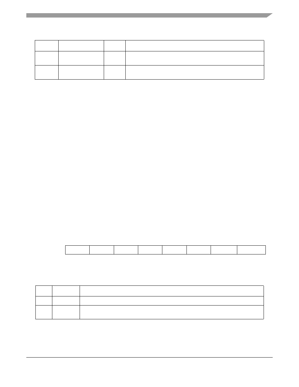
For channels running on IMA links with IDCR mode enabled, events are reported and masked in the IDSR
and IDMR registers associated with the IDCR master clock. Furthermore, these events are signalled via
the associated IDMAx bit in the SIPNR_L register. The fields of the IDSR and IDMR registers are shown
in
Note that INTO1/GRLI and INTO0/GBPB occupy the same bits in the register. Events of either type will
cause this bit to be set. It is therefore recommended that if the global buffer pool feature is used for
channels running on IMA links in IDCR mode, then the user should not use interrupt queues 1 and 0 for
receive or transmit events from these IMA links.
describes the IDSR/IDMR bit fields.
0x04
IDCRREQ
Hword
IDCR request rate. Program to [TRLR/(RNUMLINKS x 128)] x
(2048/2049).
0x06
IDCRREQF
Hword
IDCR request rate fraction. Holds the fractional portion of the IDCR
request rate, represented as (IDCRREQF / 65536).
0
1
2
3
4
5
6
7
Field
GINT3
GINT2
GINT1
GINT0
INTO3
INTO2
INTO1/GRLI INTO0/GBPB
Figure 33-30. IDMA Event/Mask Registers in IDCR Mode (IDSR/IDMR)
Table 33-27. IDSR/IDMR Field Descriptions
Bits
Name
Description
0-3
GINTx
Global Interrupt. Set when an event is sent to the corresponding interrupt queue.
4–5
INTOx
Interrupt queue overflow. Set when an overflow condition occurs in the corresponding interrupt
queue. This occurs when the CP attempts to overwrite a valid interrupt entry..
Table 33-26. IDCR Table Entry
Offset Name
Width
Description