3 hdlc channel frame reception processing, 4 hdlc parameter ram, Hdlc channel frame reception processing -3 – Freescale Semiconductor MPC8260 User Manual
Page 1227: Hdlc parameter ram -3, Fcc hdlc-specific parameter ram memory map -3
FCC HDLC Controller
MPC8260 PowerQUICC II Family Reference Manual, Rev. 2
Freescale Semiconductor
36-3
36.3
HDLC Channel Frame Reception Processing
The HDLC receiver is designed to work with almost no core intervention and can perform address
recognition, CRC checking, and maximum frame length checking. The received frame is available for any
HDLC-based protocol. When the core enables a receiver, the receiver waits for an opening flag character.
When it detects the first byte of the frame, the HDLC controller compares the frame address against the
user-programmable addresses. The user has four 16-bit address registers and an address mask available for
address matching. The HDLC controller compares the received address field to the user-defined values
after masking with the address mask. The HDLC controller can also detect broadcast (all ones) address
frames if one address register is written with all ones.
If a match is detected, the HDLC controller checks the prefetched BD; if it is empty, it starts transferring
the incoming frame to the BD’s associated buffer. When the buffer is full, the HDLC controller clears
BD[E] and generates an interrupt if BD[I] = 1. If the incoming frame is larger than the buffer, the HDLC
controller fetches the next BD in the table and, if it is empty, continues transferring the frame to the
associated buffer.
During this process, the HDLC controller checks for frames that are too long. When the frame ends, the
CRC field is checked against the recalculated value and written to the buffer. The data length written to
the last BD in the HDLC frame is the length of the entire frame. This enables HDLC protocols that lose
frames to correctly recognize a frame-too-long condition.
The HDLC controller then sets the last buffer in frame bit, writes the frame status bits into the BD, and
clears the E bit and fetches the next BD. The HDLC controller then generates a maskable interrupt,
indicating that a frame was received and is in memory. The HDLC controller then waits for a new frame.
Back-to-back frames can be received separated only by a single shared flag.
The user can configure the HDLC controller not to interrupt the core until a specified number of frames
have been received. This is configured in the received frames threshold (RFTHR) location of the parameter
RAM. This function can be combined with a timer to implement a time-out if fewer than the threshold
number of frames are received.
36.4
HDLC Parameter RAM
When an FCC operates in HDLC mode, the protocol-specific area of the FCC parameter RAM is mapped
with the HDLC-specific parameters in
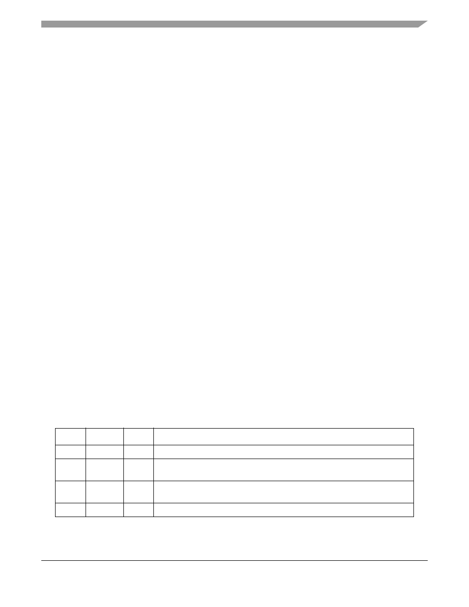
Table 36-1. FCC HDLC-Specific Parameter RAM Memory Map
Offset
1
Name
Width
Description
0x3C
—
2 Words Reserved
0x44
C_MASK
Word
CRC constant. For the 16-bit CRC-CCITT, initialize C_MASK to 0x0000_F0B8. For
the 32-bit CRC-CCITT, initialize C_MASK to 0xDEBB_20E3.
0x48
C_PRES
Word
CRC preset. For the 16-bit CRC-CCITT, initialize C_PRES to 0x0000_FFFF. For the
32-bit CRC-CCITT, initialize C_PRES to 0xFFFF_FFFF.
0x4C
DISFC
2
Hword
Discard frame counter. Counts error-free frames discarded due to lack of buffers.