Figure 30-38. atm pace control data structure, 1 apc parameter tables, Table 30-29. apc parameter table (continued) – Freescale Semiconductor MPC8260 User Manual
Page 984: Apc parameter tables -64, Atm pace control data structure -64, Apc parameter table -64, Section 30.10.4.1, “apc parameter tables
ATM Controller and AAL0, AAL1, and AAL5
MPC8260 PowerQUICC II Family Reference Manual, Rev. 2
30-64
Freescale Semiconductor
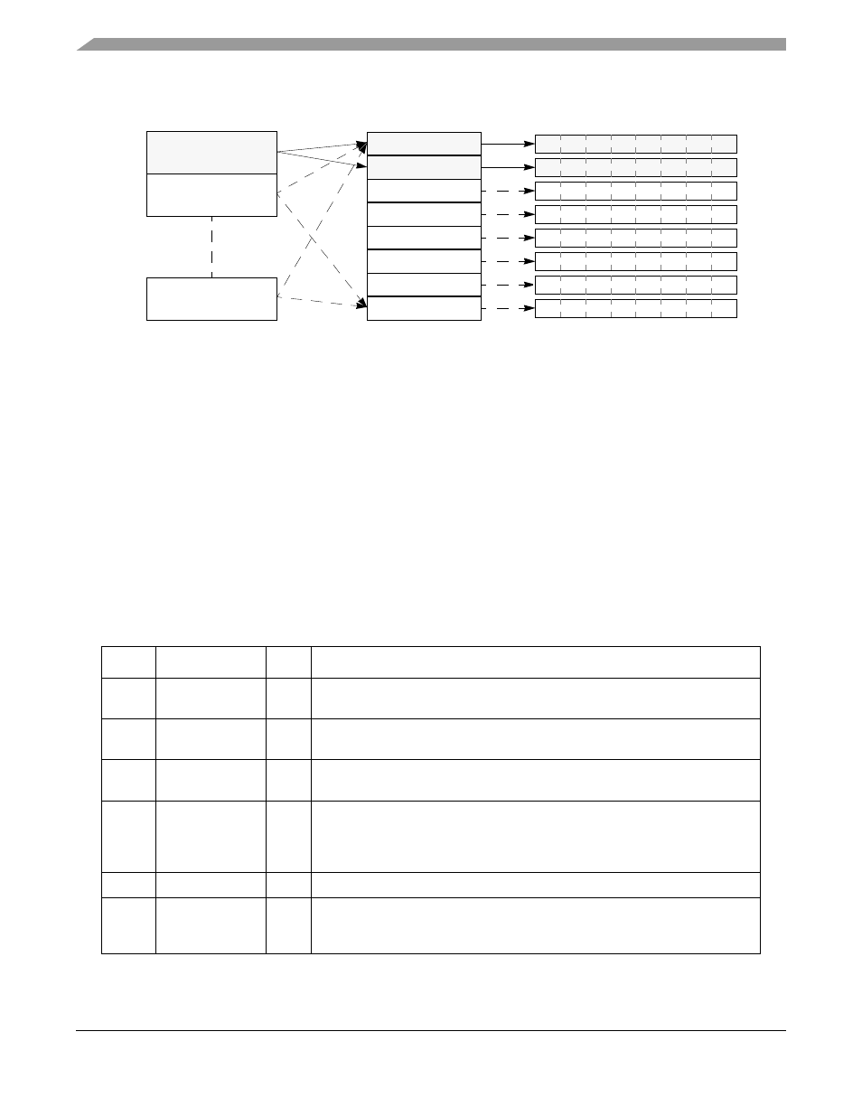
Figure 30-38. ATM Pace Control Data Structure
30.10.4.1 APC Parameter Tables
Each PHY’s APC parameter table, shown in
, holds parameters that define the priority table
location, the number of priority levels, and other APC parameters. The table resides in the dual-port RAM.
The parameter APCP_BASE, described in
Section 30.10.1, “Parameter RAM,”
points to the base address
of PHY#0’s parameter table.
For multiple PHYs, the table structure is duplicated. Each table resides in 32 bytes of memory. The starting
address of each APC parameter table is given by APCP_BASE + PHY#
× 32. Note however that in slave
mode with multiple PHYs, the parameter table always resides at APCP_BASE regardless of the PHY
address.
Table 30-29. APC Parameter Table
Offset
1
Name
Width
Description
0x00
APCL_FIRST
Hword Address of first entry in the priority table. Must be 8-byte aligned.
User-initialized.
0x02
APCL_LAST
Hword Address of last entry in the priority table. Must be 8-byte aligned. User-initialized
as APCL_FIRST + 8 x (number_of_priorities - 1).
0x04
APCL_PTR
Hword Address of current priority entry used by the CP. User-initialized with
APCL_FIRST.
0x06
CPS
Byte
Cells per slot. Determines the number of cells sent per APC slot. See
Section 30.3.2, “APC Unit Scheduling Mechanism
.” User-defined. (0x01 = 1 cell;
0xFF = 255 cells.)
Note: If ABR is used, CPS must be a power of two.
0x07
CPS_CNT
Byte
Cells sent per APC slot counter. User-initialized to CPS; used by the CP.
0x08
MAX_ITERATIO
N
Byte Max iteration allowed. Number of scan iterations allowed in the APC.
User-defined. This parameter limits the time spent in a single APC routine,
thereby avoiding excessive APC latency.
Priority 1
APC Priority Table
APC Parameter Tables
Parameter Table
PHY #0
Parameter Table
PHY #1
Parameter Table
PHY #31
Priority 2
Priority 3
Priority 4
Priority 5
Priority 6
Priority 7
Priority 8
APC Scheduling Tables
Priority 1 Scheduling Table
Priority 2 Scheduling Table
Priority 3 Scheduling Table
Priority 4 Scheduling Table
Priority 5 Scheduling Table
Priority 6 Scheduling Table
Priority 7 Scheduling Table
Priority 8 Scheduling Table
Note: The shaded areas represent the active structures for an example implementation of PHY #0 with two
priorities. (The unshaded areas and dashed arrows represent unused structures.)