Figure 13-2. tap controller state machine, 3 boundary scan register, Boundary scan register -3 – Freescale Semiconductor MPC8260 User Manual
Page 535: Tap controller state machine -3
IEEE 1149.1 Test Access Port
MPC8260 PowerQUICC II Family Reference Manual, Rev. 2
Freescale Semiconductor
13-3
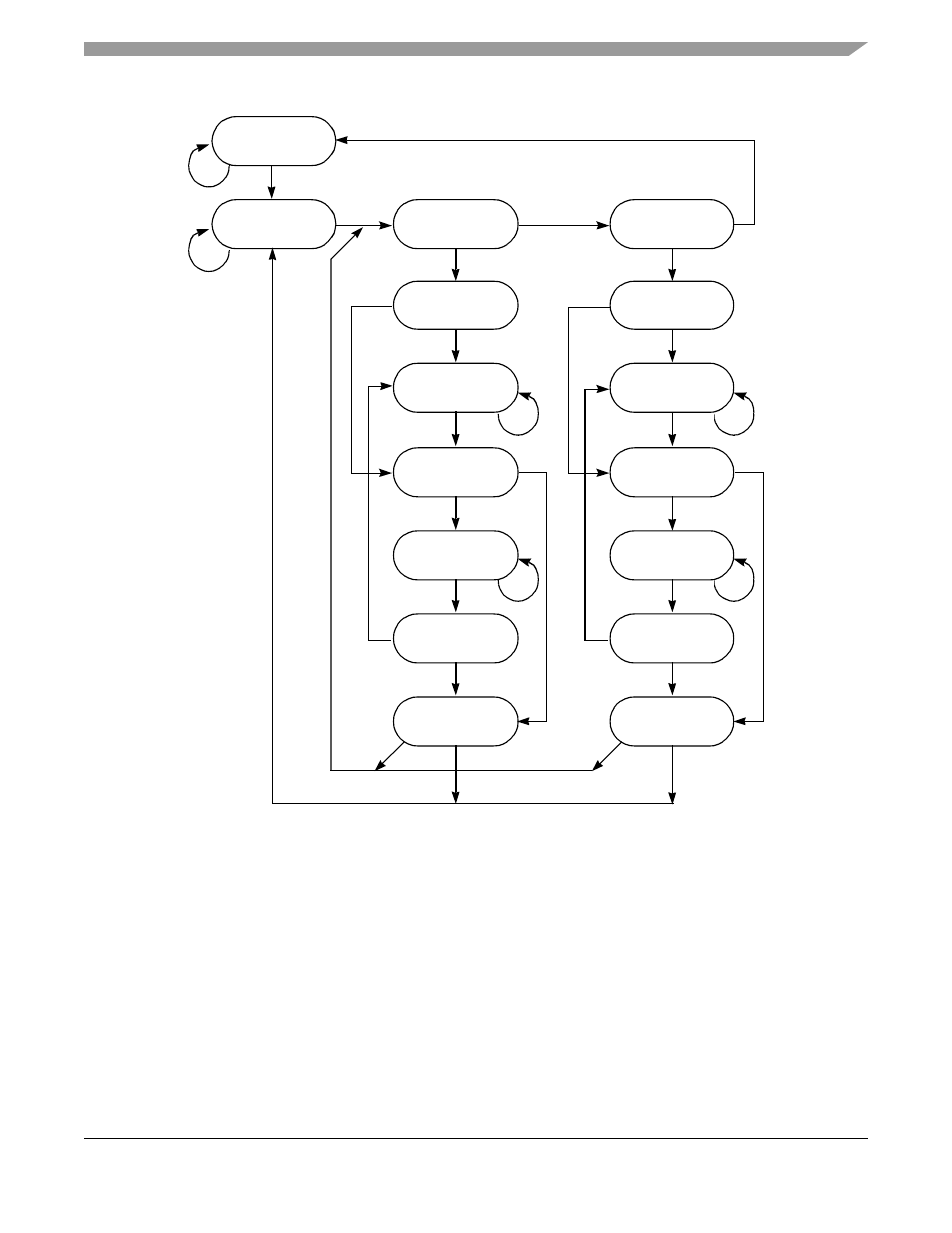
Figure 13-2. TAP Controller State Machine
13.3
Boundary Scan Register
The PowerQUICC II’s scan chain implementation has a 878-bit boundary scan register that contains bits
for all device signal, clock pins, and associated control signals. The PORESET_B and XFC pins are
associated with analog signals and are not included in the boundary scan register. An
IEEE-1149.1-compliant boundary-scan register has been included on the PowerQUICC II that can be
connected between TDI and TDO when EXTEST or SAMPLE/PRELOAD instructions are selected. It is
used for capturing signal pin data on the input pins, forcing fixed values on the output signal pins, and
selecting the direction and drive characteristics (a logic value or high impedance) of the bidirectional and
three-state signal pins.
,
,
, and
show various cell types.
Test Logic
Reset
Run—Test/Idle
Select—DR_SCAN
Capture—DR
Shift—DR
Exit1—DR
Pause—DR
Exit2—DR
Update—DR
Select—IR_SCAN
Capture—IR
Shift—IR
Exit1—IR
Pause—IR
Exit2—IR
Update—IR
0
0
0
0
1
1
1
0
0
0
0
1
1
1
1
1
0
0
1
1
1
1