5 aal1 ces protocol-specific rct, 6 aal2 protocol-specific rct, 3 transmit connection table (tct) – Freescale Semiconductor MPC8260 User Manual
Page 970: Aal1 ces protocol-specific rct -50, Aal2 protocol-specific rct -50, Transmit connection table (tct) -50, Transmit connection table (tct) entry -50, Figure 30-30 shows the format of an tct entry
ATM Controller and AAL0, AAL1, and AAL5
MPC8260 PowerQUICC II Family Reference Manual, Rev. 2
30-50
Freescale Semiconductor
30.10.2.2.5
AAL1 CES Protocol-Specific RCT
Refer to
Section 31.9.1.1, “AAL1 CES Protocol-Specific RCT.”
30.10.2.2.6
AAL2 Protocol-Specific RCT
Refer to
Section 32.4.4.1, “AAL2 Protocol-Specific RCT.”
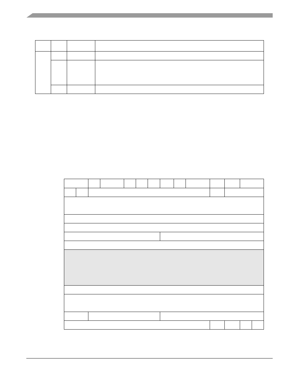
30.10.2.3 Transmit Connection Table (TCT)
shows the format of an TCT entry.
0x18
0–7
—
Reserved, should be cleared.
8
RXBM
Receive buffer interrupt mask
0 The receive buffer event of this channel is masked. (The RXB event is not sent to the
interrupt queue when receive buffers are closed.)
1 The receive buffer event of this channel is enabled.
9–15
—
Reserved, should be cleared.
0
1
2
3
4
5
6
7
8
9
10
11
12
13
14
15
Offset + 0x00
—
GBL
BO
—
DTB
BIB AVCF
—
ATT
CPUU VCON
INTQ
Offset + 0x02
—
INF
—
ABRF
AAL
Offset + 0x04
Tx Data Buffer Pointer (TXDBPTR)
Offset + 0x06
Offset + 0x08
TBDCNT
Offset + 0x0A
TBD_OFFSET
Offset + 0x0C
Rate Remainder
PCR Fraction
Offset + 0x0E
PCR
Offset + 0x10
Protocol Specific
• For AAL5,
Section 30.10.2.3.1, “AAL5 Protocol-Specific TCT
.”
• For AAL2,
Section 32.3.5.1, “AAL2 Protocol-Specific TCT
.”
• For AAL1,
Section 30.10.2.3.2, “AAL1 Protocol-Specific TCT
• For AAL1 CES,
Section 31.9.2.1, “AAL1 CES Protocol-Specific TCT
”
• For AAL0,
Section 30.10.2.3.3, “AAL0 Protocol-Specific TCT
Offset + 0x12
Offset + 0x14
Offset + 0x16
APC Linked Channel (APCLC)
Offset + 0x18
ATM Cell Header (VPI,VCI,PTI,CLP)
Offset + 0x1a
Offset + 0x1C
—
PMT
TBD_BASE
Offset + 0x1E
TBD_BASE
BNM
STPT
IMK
PM
Figure 30-30. Transmit Connection Table (TCT) Entry
Table 30-20. AAL0-Specific RCT Field Descriptions (continued)
Offset
Bits
Name
Description