Figure 31-17. pre-overrun sequence, Pre-overrun sequence -19 – Freescale Semiconductor MPC8260 User Manual
Page 1035
ATM AAL1 Circuit Emulation Service
MPC8260 PowerQUICC II Family Reference Manual, Rev. 2
Freescale Semiconductor
31-19
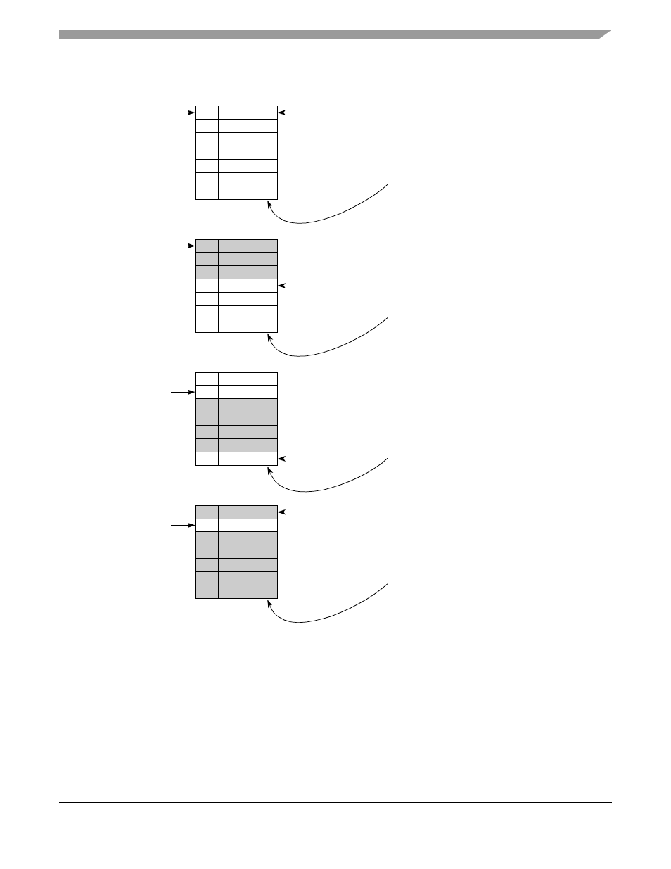
Figure 31-17. Pre-Overrun Sequence
BD 1
BD 2
BD 3
BD 4
BD 5
MCC Tx pointer
0
0
0
0
0
ATM-to-TDM
Step 1:
Initialize the MCC and ATM pointers
to the same BD table.
CESAC=0
MCC_Start=3, MCC_Stop=1
BD 6
0
BD 7
0
ATM_Start=5, ATM_Stop=7-1=6
MCC_Start
ATM Rx pointer
BD table
W
BD 1
BD 2
BD 3
BD 4
BD 5
MCC Tx pointer
1
1
1
0
0
ATM-to-TDM
Step 2:
When CESAC reaches MCC_Start,
the MCC starts transmitting.
CESAC=3
MCC_Start=3, MCC_Stop=1
BD 6
0
BD 7
0
ATM_Start=5, ATM_Stop=7-1=6
MCC_Start
ATM Rx pointer
BD table
W
BD 1
BD 2
BD 3
BD 4
BD 5
MCC Tx pointer
0
0
1
1
1
ATM-to-TDM
Step 3:
The MCC reads the data slower than
the ATM fills it. The ATM points to the
CESAC=4
MCC_Start=3, MCC_Stop=1
BD 6
1
BD 7
0
ATM_Start=5, ATM_Stop=7-1=6
ATM Rx pointer
BD table
W
last BD in the common BD table.
Step 4:
The ATM wraps around, and CESAC
reaches the ATM_Stop threshold. The
ATM write pointer freezes on the
current BD.
The MCC continues to process the
valid data. When the CESAC falls to the
ATM_Start threshold, the ATM advances
BD 1
BD 2
BD 3
BD 4
BD 5
MCC Tx pointer
1
0
1
1
1
ATM-to-TDM
BD 6
1
BD 7
1
ATM_Start
ATM Rx pointer
BD table
W
CESAC=6
to the first BD after EOSF.
Step 5:
After CESAC reaches the ATM_Start
threshold and the ATM advances to the
BD after EOSF, the ATM resynchronizes
and starts to receive valid data using
the new BD (start of SF).