5 scc bisync commands, Scc bisync commands -4 – Freescale Semiconductor MPC8260 User Manual
Page 754
SCC BISYNC Mode
MPC8260 PowerQUICC II Family Reference Manual, Rev. 2
23-4
Freescale Semiconductor
GSMR[MODE] determines the protocol for each SCC. The SYN1–SYN2 synchronization characters are
programmed in the DSR (see
Section 20.1.3, “Data Synchronization Register (DSR).”
) The BISYNC
controller uses the same basic data structure as other modes; receive and transmit errors are reported
through their respective BDs. There are two basic ways to handle BISYNC channels:
•
The controller inspects the data on a per-byte basis and interrupts the core each time a byte is
received.
•
The controller can be programmed so software handles the first two or three bytes. The controller
directly handles subsequent data without interrupting the core.
23.5
SCC BISYNC Commands
Transmit and receive commands are issued to the CP command register (CPCR). Transmit commands are
described in
.
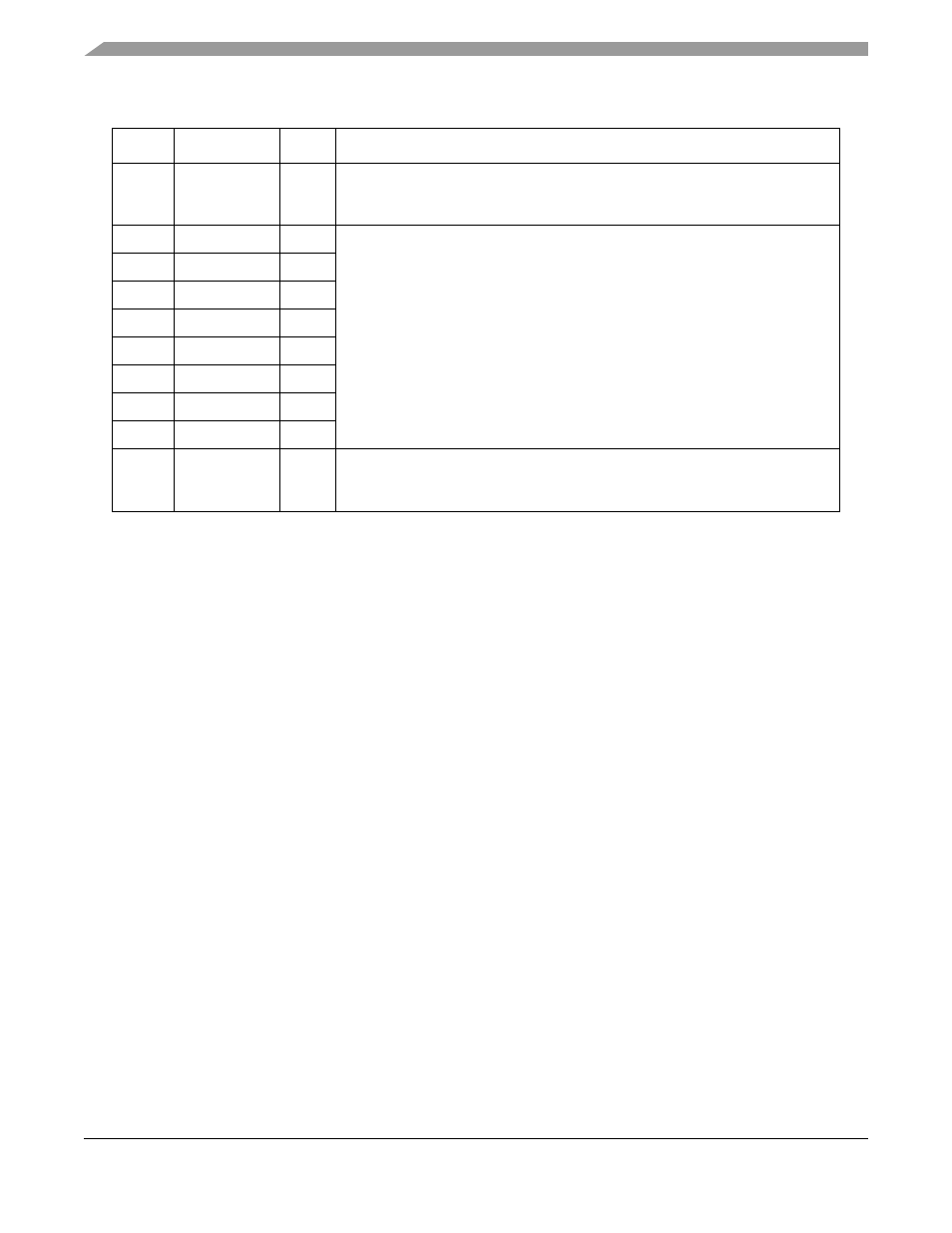
0x40
BDLE
Hword BISYNC DLE register. Contains the value to be sent as the first byte of a
DLE–SYNC pair and stripped on receive. See
.”
0x42
CHARACTER1
Hword Control character 1–8. These values represent control characters that the
BISYNC controller recognizes. See
Section 23.6, “SCC BISYNC Control
0x44
CHARACTER2
Hword
0x46
CHARACTER3
Hword
0x48
CHARACTER4
Hword
0x4A
CHARACTER5
Hword
0x4C
CHARACTER6
Hword
0x4E
CHARACTER7
Hword
0x50
CHARACTER8
Hword
0x52
RCCM
Hword Receive control character mask. Masks CHARACTER
n
comparison so control
character classes can be defined. Setting a bit enables and clearing a bit masks
comparison. See
Section 23.6, “SCC BISYNC Control Character Recognition
1
From SCC
x
base address. See
Section 20.3.1, “SCC Base Addresses
.”
Table 23-1. SCC BISYNC Parameter RAM Memory Map
Offset
1
Name
Width
Description